CNC MILLING & TURNING
Precision CNC.
Built for the fit.
Made to your drawing.
CNC machining for custom mold components.
From complex inserts to replacement cores,
built around the fit your mold needs.
Drawing review · Milling & turning · Feature inspection
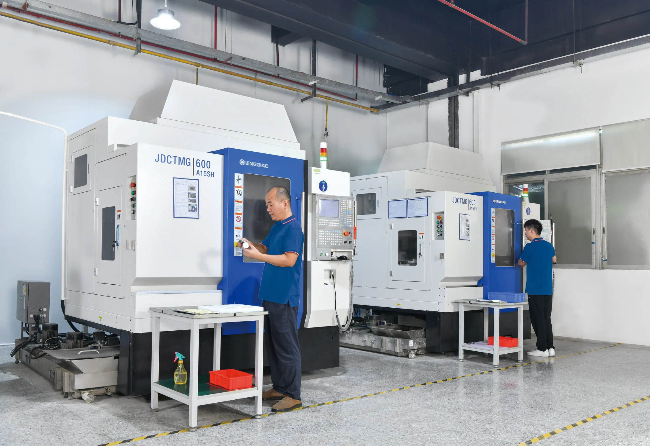
SENLAN / CNC milling workshop
01 / MACHINING CAPABILITY
Room for the geometry.
Focus on the detail.
From slender pins to larger mold inserts, the working range is a starting point. We review your geometry, material and holding requirements to confirm the route.
Milling
Length max. / mm
Milling
Width max. / mm
Milling
Height max. / mm
Turning
Diameter max. / mm
Turning
Length max. / mm
Recorded machining ranges in mm; turning diameter starts at 1 mm. These figures describe process capacity, not individual machine-axis travel. Final feasibility is reviewed against your drawing.
OUR CNC EQUIPMENT
Milling and turning, in the same workshop.
Hover or tap to explore
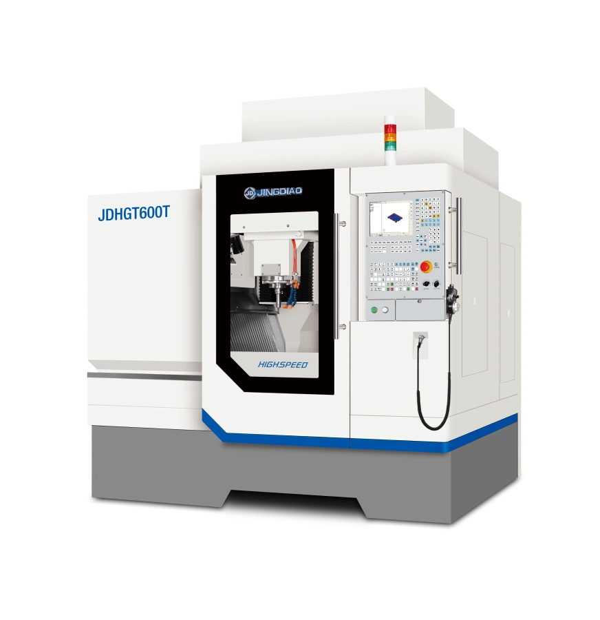
7 units
JINGDIAO
JDHGT600T series reference image
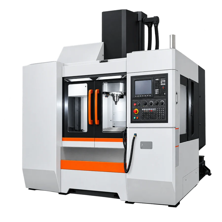
3 units
BAOFENG
AI illustration · based on equipment reference
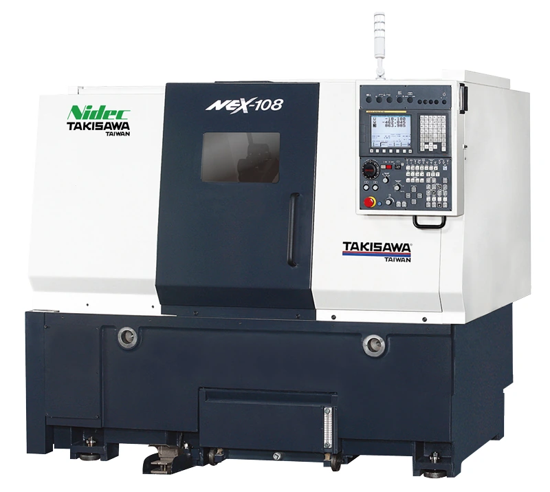
4 units
TAKISAWA / NEX
NEX-108 manufacturer image
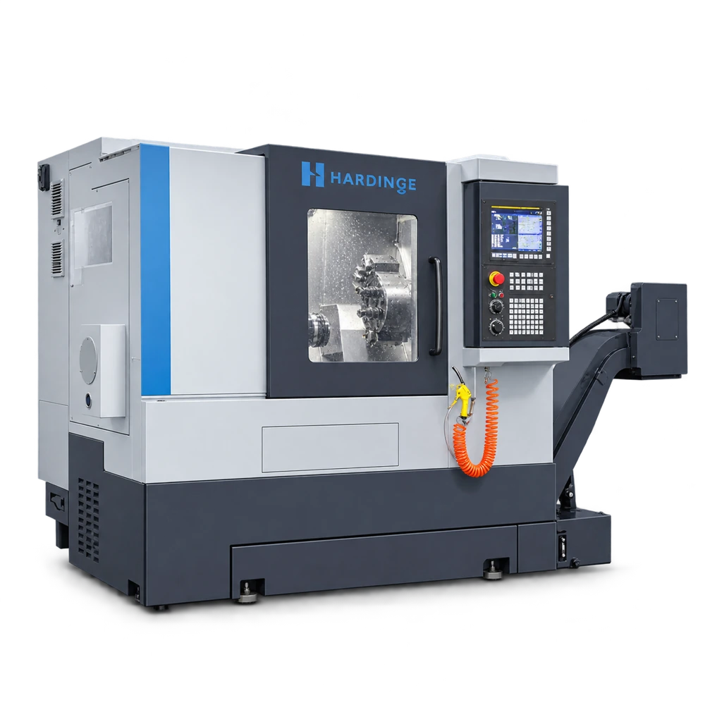
2 units
HARDINGE
AI illustration based on workshop reference
THE COMPLETE MANUFACTURING PICTURE
Manufacturing & Quality ↗
Materials, sourcing, customer connections and inspection resources.
02 / FROM DRAWING TO COMPONENT
The detail is in
the decisions.
For moldmakers handling complex parts, replacement work or additional capacity. Explore what we review at each stage—and what your drawing needs to tell us.
01 / START WITH THE FUNCTION
Plan around the features
that have to fit.
A new insert, a replacement core and a repeat batch need different questions answered. We review the drawing revision, mating features and supplied condition before selecting the machining sequence.
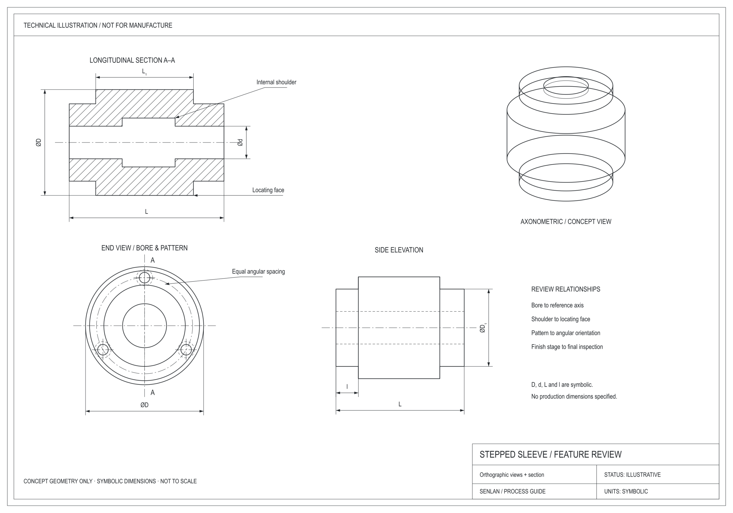
Choose milling, turning—or both.
Flats, pockets and accessible cavities usually lead to milling. Related diameters, bores and shoulders lead to turning. Parts with both feature types need an agreed datum transfer between setups.
Flag the features that control assembly.
Identify sealing faces, locating shoulders, thread interfaces, matched diameters and any dimensions linked to another component. Tell us which features are critical to the fit so they can guide the process and inspection plan.
Define the job: new, replacement or repeat.
For replacements, add the mating-part information and the known fit problem; an old part can help identify interfaces but may include wear. For repeat work, confirm the latest revision, quantity and any changed acceptance requirements.
A useful drawing review resolves a decision.
It should clarify how a critical feature will be made and checked, or identify a detail that needs your confirmation. Material, hardness, quantity and delivery needs belong in the same review.
Your input
2D drawing + 3D model
Our review
Geometry, datums & access
Agree before cutting
Scope, sequence & checks
02 / CAVITIES, CONTOURS & LOCATING FACES
Make the surface.
Keep the reference.
Milling creates the planes, pockets, slots and accessible 2D/3D contours of an insert. The sequence must also preserve the reference surfaces used for finishing and assembly.
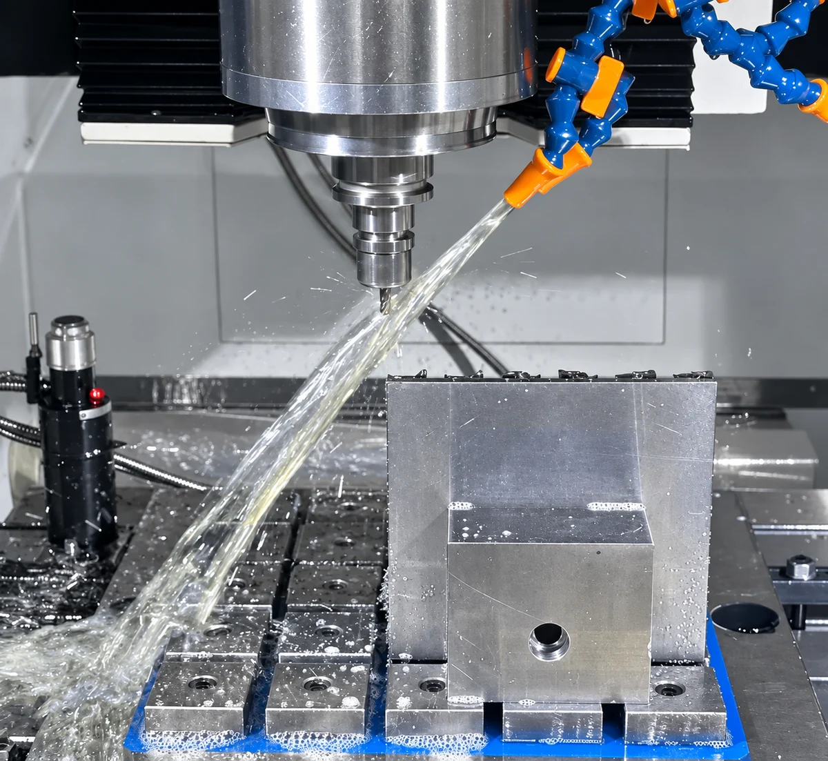
Internal corners and deep pockets
Tool diameter determines the radius a cutter can leave. Depth and reach affect rigidity and access. Sharp internal features or inaccessible details may need an EDM operation after milling.
Hole patterns and thin sections
Review hole locations from the specified datums, including intersecting passages. Thin walls and small edges need a support and cutting sequence that considers movement during machining and unclamping.
Roughing, treatment and finish milling
The supplied steel condition and required final hardness determine when treatment and finishing belong in the route. Leave the agreed stock for grinding, EDM or polishing; roughing allowance is not the finished tolerance.
From the process records
Recorded finish-milling work includes locating shoulders on insert and pin components. The important question is which face establishes the next setup and which relationships must survive that handover.
Establish
Locating face & orientation
Machine
Pockets, planes & contours
Hand over
Finishing stock & datums
03 / BORES, THREADS & RELATED DIAMETERS
One functional axis.
Several critical features.
Cores, pins and sleeves often combine turned geometry with threads, flats or cross holes. We plan the grip, support and subsequent operations around the relationships shown on the drawing.
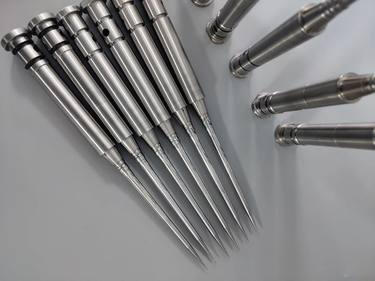
Diameters, shoulders and threads
Review each critical diameter, shoulder and thread against the functional axis. For suitable components, Hardinge turning and thread machining can share a setup, reducing the need to re-establish the relationship between these features.
Long pins and thin-walled sleeves
Grip length, support, bore reach and wall thickness affect how a part can be held. A temporary clamping area or a different cutting sequence may be needed before the final end or wall is finished.
Flats, cross holes and the next setup
Off-axis features may follow on a milling operation. Define the locating face, axis and angular orientation before transfer, and preserve the stock needed by any later EDM, grinding or polishing step.
For threaded or mating components
Include the thread specification, mating requirements and how the part will be checked. A nominal thread callout alone may not explain the assembly fit you need.
Locate
Functional axis & shoulder
Support
Grip length & slender areas
Transfer
Angular reference & stock
04 / CONTROL THE HANDOVER
Carry the reference
through the whole route.
CNC machining may establish the geometry while EDM, grinding or polishing completes specific features. The handover should define the datum, remaining stock and next inspection point.
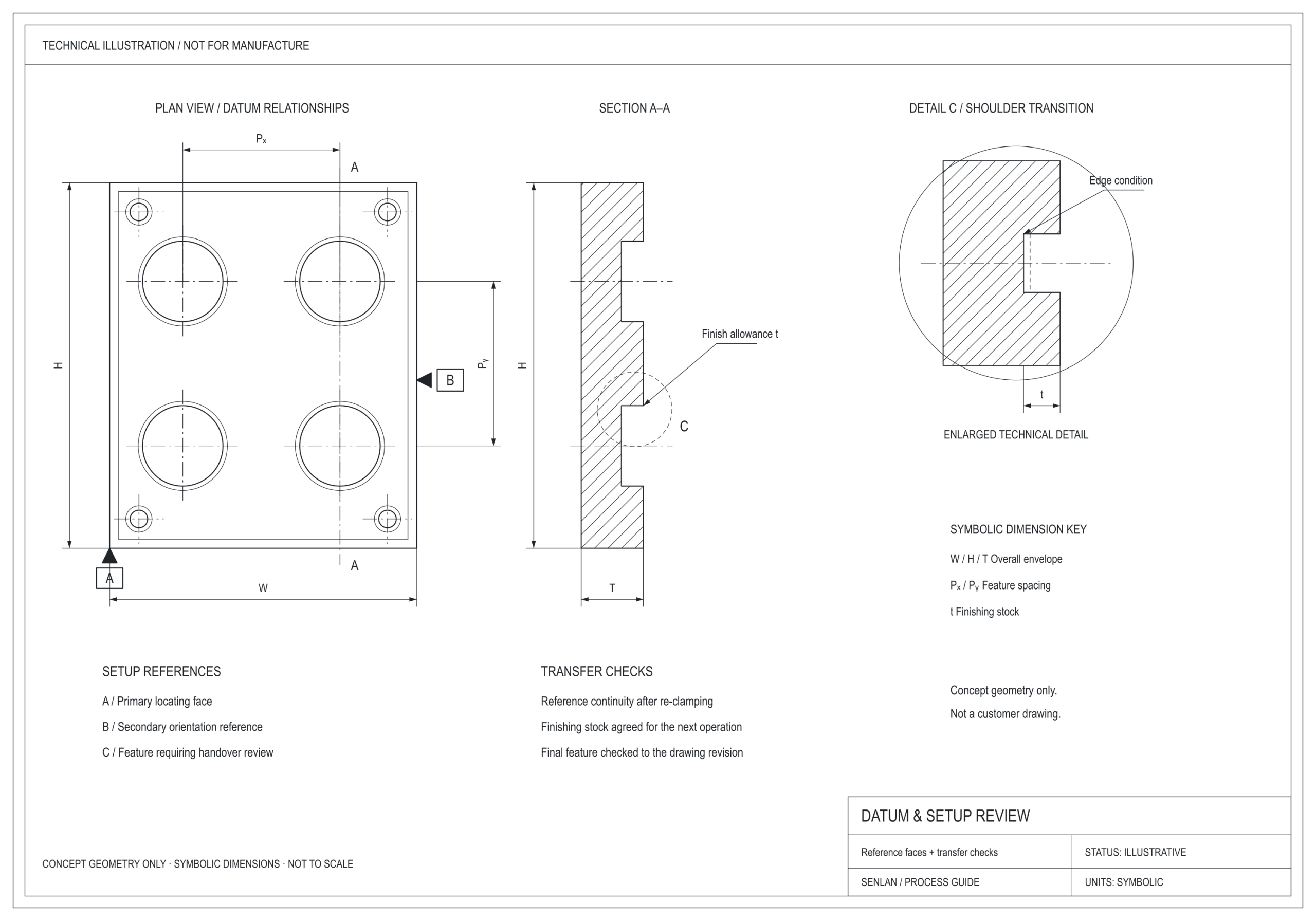
Retain a clamping area
A central-core process record calls for a reserved holding area. Removing it too early can make a later setup harder to locate. Plan when that temporary feature is removed and how the finished end will be checked.
Reserve access for EDM
A local-bore process record includes an EDM handover. Cutter access, electrode access and the surface used to position the workpiece must be considered together rather than treating the operations as unrelated steps.
Preserve finishing stock
Sleeve and cavity records specify remaining stock for later finishing. Set the amount by feature and operation, taking material condition and treatment sequence into account. Confirm the final size after the relevant finishing stage.
A route is more than a list of machines.
State who completes each operation, the condition in which the part moves on, and the feature checked at that point. These process excerpts describe machining tasks, not acceptance results for the pictured part.
Establish
Axis, face & orientation
Preserve
Grip & finishing allowance
Verify
Relationships at handover
05 / CLOSE THE LOOP
Check the fit.
Record what matters.
The inspection plan connects each critical requirement to its datum, measurement method and manufacturing stage. Repeat work also needs a clear record of the accepted revision and fit requirements.
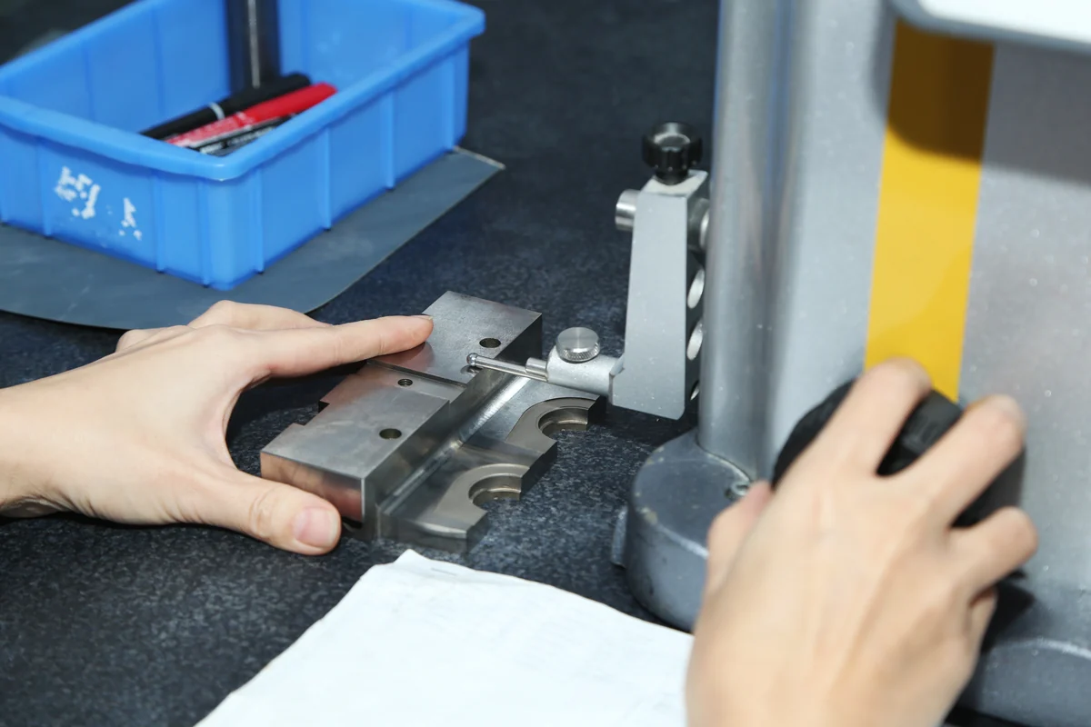
First-piece and in-process decisions
Agree which features need checking before the next operation makes correction difficult. Match the measurement method to the requirement: size, axis relationship, profile, thread or surface condition.
Final checks and documentation
Specify the dimensions and geometric relationships to report, plus any material or heat-treatment documentation. Link the report to the part identification and drawing revision so the receiving team can use it.
Replacement and multi-cavity consistency
For a replacement, review the original dimension chain and mating component; do not simply copy a worn surface. For multi-cavity or repeat parts, control the revision, setup references and inspection criteria across the set.
Application focus · interchangeable components
A recorded 32-set closure-core project included a first-piece review followed by repeat orders. It illustrates the importance of consistent setup references and inspection criteria across a set. The requirements for your component are agreed against its own drawing.
Define
Critical features & method
Check
First piece, process & final
Record
Part ID, revision & report
Explore by component.
Choose the geometry closest to your drawing.
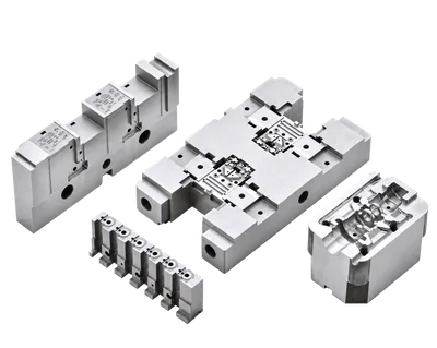
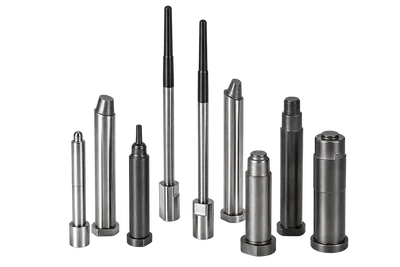
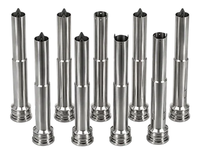
Component examples · images include AI-assisted cutouts and refinements.
03 / DRAWING REVIEW
Let’s look at
your critical feature.
New component, replacement part or repeat batch.
Tell us what has to fit—and when you need it.
A useful enquiry starts with:
Drawing & model
Current 2D revision and available 3D data.
Material & critical features
Grade, hardness, mating requirements and surface finish.
Quantity, timing & reports
Batch size, required date and inspection documents.
We review the scope before confirming feasibility and quotation.
Before quotation.
What should I send for a CNC quotation?
Send the current 2D drawing and available 3D model, material and condition, quantity, required date, and the features most important to fit. Add inspection and documentation requirements, plus mating-part details for replacements.
Can you quote a tolerance before seeing the drawing?
Tolerance depends on the feature, size, material condition, holding method, finishing route and measurement method. Highlight critical requirements in the drawing so the quote can address the actual component.
Can CNC be combined with EDM, grinding or polishing?
Yes, the route may combine processes when a feature needs different access, surface finish or final geometry. The quotation should identify the completed scope and any handover conditions.