Products / Custom mold sleeves
Sleeve Components.
Made for the fit.
Ejector sleeves. Core sleeves.
The bore, the outside diameter—and the parts they work with.
Custom sleeves made to your drawing. Bring the working surfaces, mating parts and finished condition into one review.
01 / A closer look at the geometry
Sleeve geometry example
CNC TURNING · GRINDING & FINISHING · INSPECTION
Function and fit follow the drawing.
01 / Component examples
Different profiles.
One connected fit.
See the bore, shoulders and outside profiles. Open an image for a closer look and compare it with the source photograph.
Showing all 4 examples
01 / Bore & guiding length
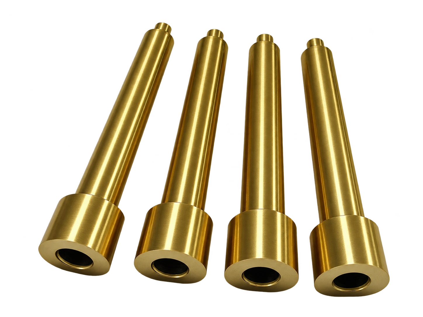
Long tubular profiles
Flanged ends, long outside profiles and visible bores.
Product geometry example · source photo available
02 / Shoulders & locating faces
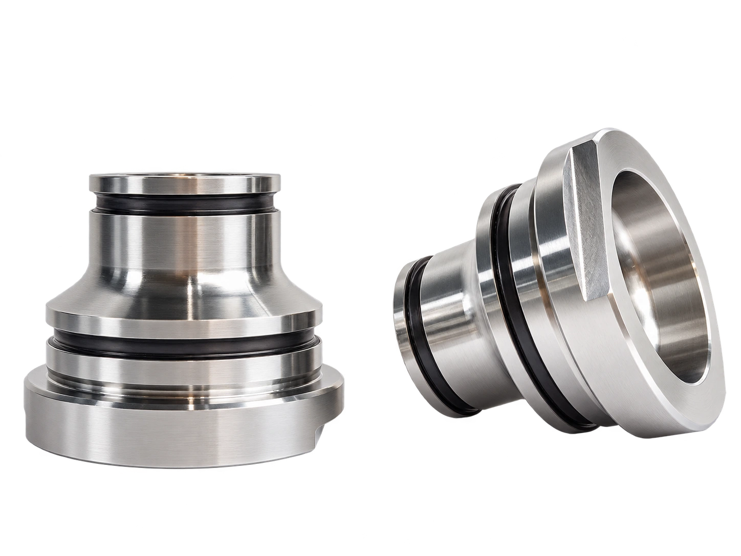
Stepped sleeve geometry
Short metal components with shoulders, flanges and central bores.
Product geometry example · source photo available
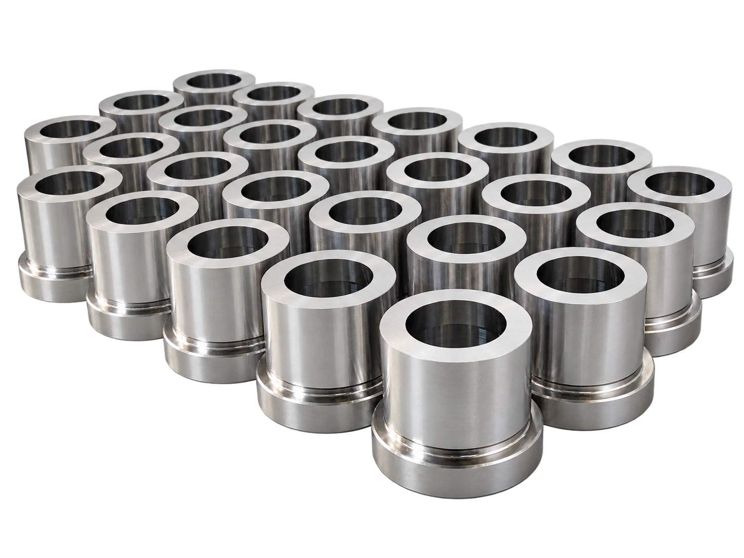
03 / Connected surfaces
Bores & outside diameters
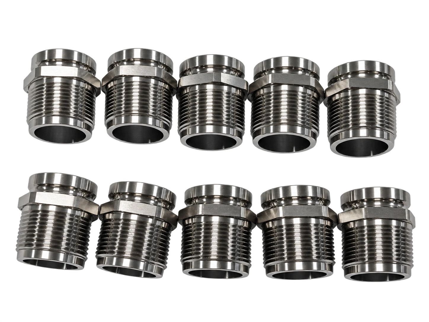
A group of sleeve components with bores and stepped outside profiles.
Product geometry example · source photo available
04 / Steps & external features
Short threaded profiles
Short sleeve geometry with external threads and end features.
Product geometry example · source photo available
Open a photograph to compare the source. Dimensions and fit requirements follow your drawing.
02 / Function & fit
Read the sleeve
with its mating part.
Start with the surfaces that guide, locate, form or eject. A sleeve name alone does not describe the complete interface.
Review the guiding bore, mating pin, contact face and working stroke.
Connect the forming end to the locating diameter, shoulder and reference face.
Separate the original fit intent from wear measured on a used part.
For ejection & sliding
Send the sleeve and mating-pin drawings.
Mark the guiding length, moving surfaces, return position and intended fit.
For forming & locating
Identify the forming surface and its references.
Show the locating bore or OD, axial shoulder, adjacent forming geometry and finish zones.
For replacement & wear
Keep wear separate from the original specification.
Send the original drawing, used-part photos, wear location and mating-part information.
Ejector sleeves: guiding, ejection & wear
Ejector sleeves and core sleeves share many dimensional requirements. The difference is the job their working surfaces perform. A sleeve may combine functions, so include an assembly view rather than relying on its name alone.
EJECTION & SLIDING
Ejector Sleeves
Move around a mating pin or core to push a molded feature from the mold. The guiding bore, outside guiding diameter, ejection face and stroke relationship belong in the same review.
Working interface
Moving sleeve, mating pin and guiding bore
Critical areas
Sliding length, contact face, bore and guiding OD
Useful input
Mating dimensions, travel direction and operating conditions
FORMING & FITTING
Core Sleeves
Provide forming or fitting features around a core or insert. Identify which surface forms the molded part, which diameter locates the sleeve and which face establishes its axial position.
Working interface
Sleeve, core or insert and surrounding locating bore
Critical areas
Forming end, locating shoulder and connected ID/OD features
Useful input
Forming geometry, assembly section and fit requirements
A sleeve can push around a circular feature while a central pin or core remains in place. Show the moving and stationary parts, the supported length and the return position. That context helps separate a sliding area from a relieved or non-contact area.
Read the sleeve together with its pin.
Fit depends on the finished mating diameters, guiding length and the condition of both surfaces.
Bore and guiding diameter
Identify every diameter that guides the sleeve and the axial length over which the fit applies. Specify the intended clearance or fit on the drawings of both parts. An isolated sleeve diameter does not define the assembled clearance.
Ejection face and stroke
Mark the face that contacts the molded part, the working length and the reference used to set its position. Include the required edge condition. Available stroke and mechanism motion remain mold-design inputs; component manufacture does not establish an ejection-performance guarantee.
Wear, binding and replacement
Share the worn area, scoring location or point at which movement becomes tight. Clearance, alignment, surface condition and operating conditions should be assessed together. For a replacement, distinguish the intended drawing size from wear measured on the used sleeve or pin.
Core sleeves: forming, location & finish
A core sleeve is reviewed in the assembly around its core or insert. The drawing must identify the forming region; a short hollow or stepped part is not automatically a forming sleeve.
Define the forming area on the drawing.
The visible bore and shoulders explain the geometry, not the application or material grade.
Forming end and local geometry
Show the molded-part contact surfaces, steps, radii, reliefs and any contour that continues into the adjoining component. Specify which edges are functional and which may be broken. Where a forming interface is split between parts, identify the intended joint and its acceptance criteria.
Radial and axial location
The locating OD or bore controls radial position; a shoulder or end face may establish axial position. Mark those references explicitly and connect the forming geometry to them. Review the pin, insert and surrounding bore where their tolerances affect the assembly.
Surface finishing
Identify forming, fitting and non-functional areas separately. Specify the required surface finish and any permitted finishing direction. Polishing must preserve the drawing-defined geometry and edges; “polish all surfaces” can leave the functional scope unclear.
ID / OD, wall thickness, steps & length
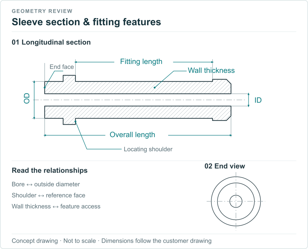
A mold sleeve is defined by connected features. Mark the functional diameter at each section and state whether the requirement applies before or after heat treatment, coating or final finishing.
- Inside and outside diametersSpecify the size, tolerance and functional length of each bore and OD. Distinguish a working fit from a clearance or relief area.
- Wall thickness and bore accessShow local thin sections, bore depth and transitions. Thin walls affect workholding and deformation risk; bore diameter and depth affect tool and measurement access.
- Shoulders, grooves and reliefsDimension the locating steps and groove positions from the intended datum. Identify relief needed for tool clearance and any corner radius controlled by the mating component.
- End faces and lengthSeparate overall length from working projection or shoulder-to-face length. Identify the face that locates, forms or ejects and its required relationship to the datum.
Datums, alignment & connected parts
Provide the datum axis or reference diameter, the axial locating face and the geometric controls that connect the bore, outer features and forming or ejection face. Diameter size alone does not establish their alignment.
Roundness describes the form of a circular section. Runout is assessed relative to a datum during rotation. Straightness and axis relationships address other aspects of the feature. State the required control and drawing standard so the inspection setup matches the design intent.
If “concentric” or “coaxial” appears only as a note, clarify the controlled feature, reference and acceptance requirement before manufacture. No universal coaxiality value is assigned to every sleeve.
Supply the connected parts
- Mating pin or core drawing, revision and finished diameter
- Plate or insert bore and its locating face
- Engagement length, movement direction and assembly section
- Relevant material, treatment and operating conditions
State whether the scope is individual component inspection, a check with a supplied mating part, or an assembly check. These are different acceptance tasks.
A useful starting package
Drawing & revision + Functional dimensions + Mating / assembly view + Finished condition
Three end-use scenarios
From the mold.
Into everyday use.
See where molded interfaces meet daily use. Bring the product geometry and mold layout together when reviewing sleeve function and fit.

01 / Automotive connectors
Connecting a car sensor.
A sealed sensor connector brings a cylindrical housing, locating collar and seal seat into the tool review. Define the forming surfaces and release arrangement on the mold drawing.

02 / Appliance control knobs
Setting the wash cycle.
A washing-machine knob connects a molded grip to its control shaft. Review the shaft bore, hub support and the face available for ejection together with the mating geometry.

03 / Garden hose couplings
Connecting a garden hose.
A hose connector joins the water line to a spray nozzle. Review the internal passage, sealing seat and locating shoulders; the part drawing defines their relationship to the mating connector.
Typical use contexts. The part and mold drawings define the sleeve arrangement and ejection method.
03 / Manufacturing & finished condition
Plan the route.
Protect the working surfaces.
Geometry, wall thickness, bore access and the final material condition determine the sequence. The route is reviewed for each drawing.
Precision for the working interface
Drawing-defined. Feature by feature.
01 / MACHINING
0.005mm
Machining accuracy
Reference for specified sleeve dimensions; reviewed against geometry and finished condition.
02 / SURFACE FINISH
Ra0.4µm
Surface roughness
Reference for designated working surfaces. Define the finish zones and critical edges.
03 / INSPECTION
100%
Piece-by-piece checks
Every part is checked. Measurement method and report features follow the agreed scope.
Reference capability. Final values, feature access and inspection scope are confirmed against your sleeve drawing.

01 / Establish the geometry
CNC turning
Bores, outside profiles, shoulders, grooves and faces.
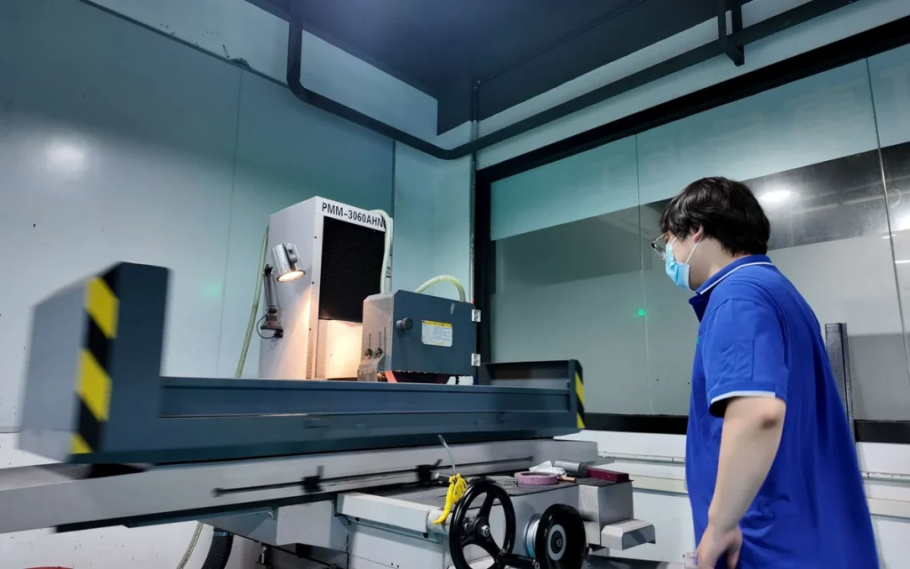
02 / Finish the interface
Grinding & finishing
Assign the finishing process to the functional features.
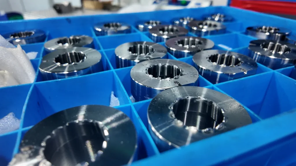
03 / Protect the surface
Handling & transfer
Keep finished components separated during handling.
Original workshop and handling photographs. Scene photographs do not document the route of a particular sleeve order.
Manufacturing sequence, allowances & outside operations
The route is selected after reviewing geometry, material condition, datums and measurement access. Turning establishes rotational features; internal and external cylindrical grinding can finish specified diameters where the geometry permits.
Establish geometry
The current equipment record lists NEX and HARDINGE CNC lathes. Turning can establish bores, ODs, shoulders, grooves and faces. Workholding, wall thickness and the sequence of internal and external operations require a part-specific review.
Plan treatment & allowance
Allowances are selected for the following operations and material condition. Heat treatment and coating, when required, are coordinated with external processing. The route must state which surfaces are finished before and after those operations.
Finish the functional diameters
The current equipment table records an internal/external cylindrical grinder. Bore access, support, datum transfer and finishing stock determine suitability. Grinding is assigned to the features that require it rather than assumed for every surface.
Check, protect & transfer
The turning work instruction calls for first-piece inspection before batch production, repeat checks during machining and protection against rust and collision during transfer. These controls address tool wear and handling risk.
Two sleeve examples, with different evidence.
COMPLETED & SHIPPED STATUS
Single-piece H13 sleeve insert
A recorded order covers one H13 sleeve insert, with 50–52 HRC and DLC specified as requirements. The production-system summary records one piece completed and shipped.
The record supports order status and quantity. Final hardness, coating and dimensional results require the corresponding documents; the forming function is not inferred from the name.
FINISH-TURNING REQUIREMENTS
Ejector sleeve machining allowances
Process records cover two ejector sleeve designs, each with a task quantity of 18. The instructions address internal and external features, remaining stock, axial allowance, surface finish and concentricity.
These are machining requirements, not measured results or a completed-delivery count. Numerical allowances remain project-specific.
Material, hardness & treatment requirements
Specify the exact material grade, hardness requirement and surface treatment from your drawing. Material names are not automatically substituted with an assumed equivalent. Share the mating material and working conditions where they affect the fit or surface selection.
The H13 record above is one order example. It does not establish a standard material, hardness or coating specification for every sleeve.
Three items to define before release
Finished dimensions
State whether ID/OD and fit requirements apply after all specified treatments. Any coating allowance must follow the agreed processing scope.
Covered and excluded surfaces
Mark treatment areas, masking or exclusion requirements and edges that must retain their geometry.
Required documents
Request material, hardness or treatment records with the relevant part and revision. External processing must remain identified in the project scope.
Measure the feature in its reference
Agree the check.
Then the acceptance scope.
The measuring method follows the feature, datum, tolerance and access. State what must be recorded before the sleeve is made.
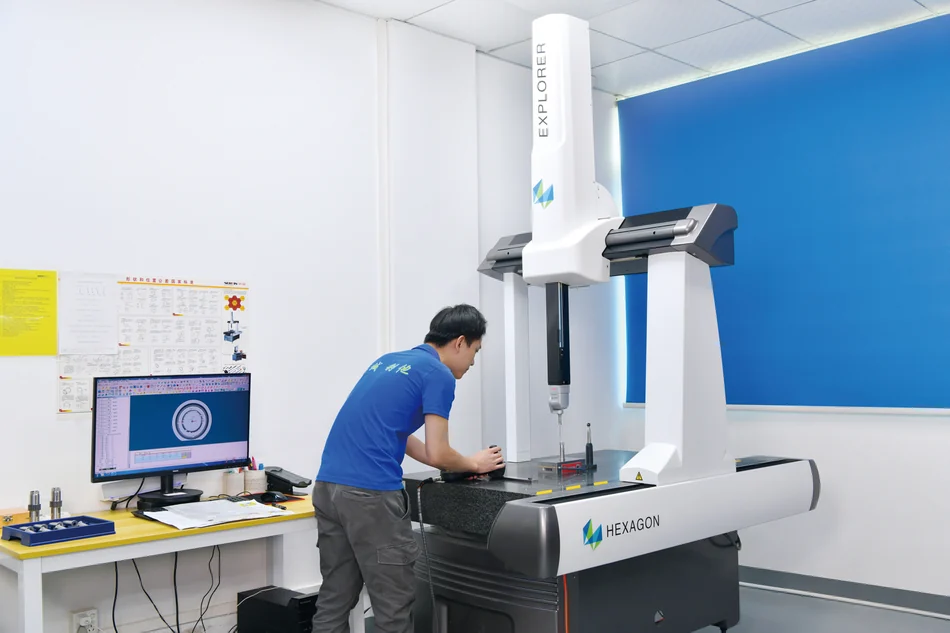
Datum relationships
Accessible positions and geometric relationships.

Rotational features
Drawing-specified form and axis relationships.
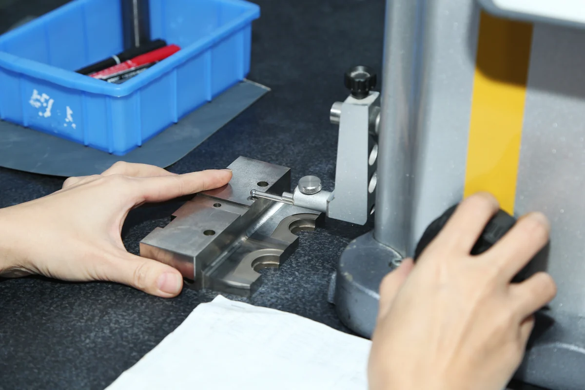
Steps & end faces
Reference faces, shoulders and working projection.
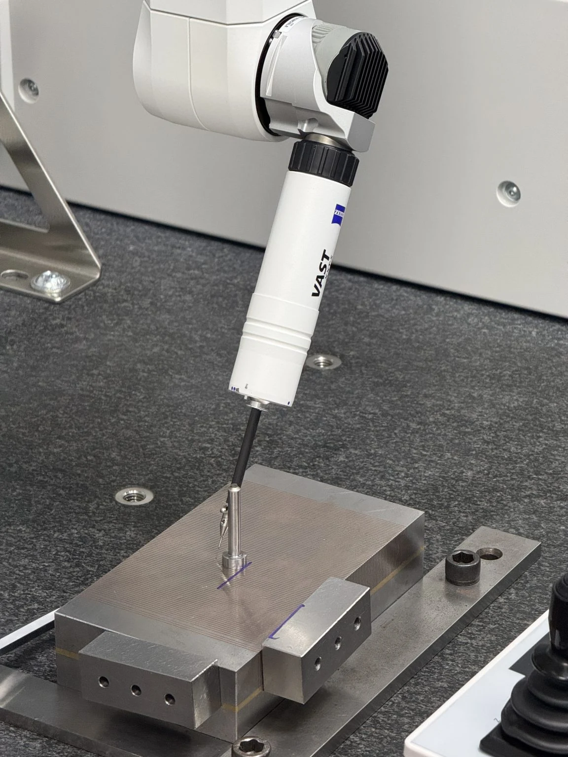
Feature access
Select a method that can reach the required feature.
Inspection scene photographs. Component checks, mold trials and customer acceptance are separate scopes.
Inspection features, methods & required records
Inspection review
- Identify the functional datums and finished condition.
- Confirm bore access and the measuring method.
- Agree the inspection report and acceptance scope.
Inspection should follow the functional datums and finished condition on the drawing. Bore size, depth and access influence the measuring method. Equipment figures do not replace the component acceptance criteria.
Feature to check
What the review needs
Acceptance boundary
ID / OD
Each working diameter, tolerance, length and finished condition; access to the bore.
Report the specified dimensions. Size results alone do not prove alignment or sliding performance.
Steps & end faces
Datum face, shoulder position, working projection and relevant geometric controls.
An overall-length measurement cannot replace every shoulder-to-face or face-orientation requirement.
Form & axis relationships
Drawing-defined roundness, runout, straightness or axis control and reference setup.
Different geometric controls require different evaluations; do not treat them as interchangeable.
Forming & sliding surfaces
Specified finish, critical edge condition and treatment area; required inspection documents.
Visual appearance does not establish a numerical roughness value, hardness or coating result.
Mating fit
Matching drawings or supplied mating parts; scope of static fit or movement checks.
A component report does not establish universal interchangeability or mold-trial success.
First piece, process checks and release records
The CNC turning instruction requires first-piece confirmation and repeat checks during production. Agree any project-specific inspection report and the features to be recorded before manufacture. Material and treatment documents should remain traceable to the relevant component.
Recorded sleeve orders: evidence & limits
Single-piece H13 sleeve insert
A recorded order covers one H13 sleeve insert. 50–52 HRC and DLC are requirements; the production-system summary records one piece completed and shipped. Final hardness, coating and dimensional results require the corresponding records.
Ejector sleeve machining allowances
Process records cover two ejector sleeve designs, each with a task quantity of 18. Internal and external features, remaining stock, axial allowance, surface finish and concentricity are machining requirements—not measured results or completed-delivery counts.
Connected component families
Review the other side
of the interface.
Bring the pin, insert or surrounding component into the review when it affects the sleeve fit.
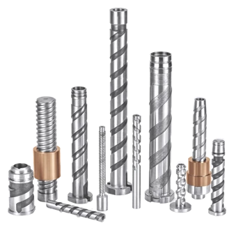
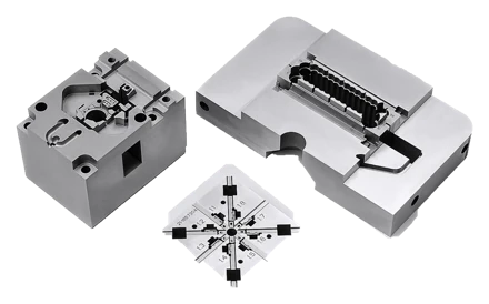
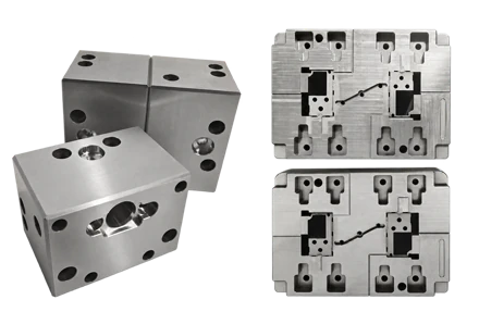
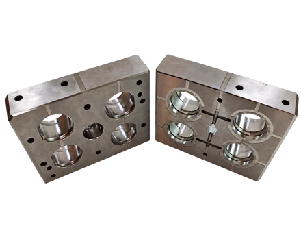
Background-removed catalogue photographs. These are general geometry examples, not a matched assembly.
04 / Your order
Bring the sleeve.
Bring the fit requirements.
New part, replacement or modification—start with the drawing and tell us what the working interface must do.
Start with the current drawing.
Include its revision, mating-part information, material and quantity.
Show the original fit and the wear.
Supply the original specification, used-part photos, mating details and the location of scoring or binding.
Mark exactly what changes.
Send the existing and proposed revisions. Identify changed dimensions and any effect on the mating parts.
A focused sleeve RFQ
Send the details
that define the fit.
- 2D drawing, available 3D model & revision
- Functional ID / OD, lengths & datums
- Mating drawings or assembly section
- Material, treatment, quantity & required records
Start with the information you have. An NDA can be requested before restricted drawings are shared.
Confirm the drawing revision, material, mating information and requested checks.
Agree the process sequence, finished condition and any external treatment scope.
Review the agreed inspection records, identification and protection before dispatch.
Replacement, binding, scoring & fit mismatch
A worn sample is useful context, but its dimensions can differ from the intended design. Send the original drawing when available and identify the conditions under which the problem occurs.
Binding or uneven movement
Mark the stroke position and contact area where movement tightens. Provide the mating pin, guiding bore, alignment references and surface condition. A tighter or looser sleeve diameter should not be selected without the assembly context.
Scoring or accelerated wear
Photograph the wear location and identify the material pair, treatment and operating conditions. Separate surface damage from the nominal drawing requirements; a coating change alone is not a verified remedy.
Mismatch at the locating or forming end
Show the shoulder stack, end-face position and adjoining forming geometry. Identify whether the concern is radial fit, axial position or the forming joint so each requirement can be reviewed separately.
Drawing review questions
How do I distinguish an ejector sleeve from a core sleeve?
Identify its working function in the assembly. A sleeve that moves to push the molded part is reviewed around ejection and sliding interfaces. A sleeve that provides forming or fitting geometry around a core or insert is reviewed around those surfaces and locating features. A component can combine both functions.
Which ID/OD and datum details are needed?
Provide each functional bore and OD, the length over which its tolerance applies, the locating face and the geometric controls between features. Add the drawing revision and finished material/treatment condition. Include a section view where steps or internal features are difficult to interpret.
Can the sleeve be reviewed together with its mating pin?
Yes—include the pin or core drawing and relevant plate or insert bore. State whether you need a drawing-based fit review, checks with supplied parts or an assembly check. Agree the scope before treating a result as proof of movement or interchangeability.
Can a used sleeve be the basis for a replacement?
A sample can support the review. Supply the original drawing, mating-part information and known wear locations where available. Measured wear must be separated from the original design intent; a sample alone may not define the required fit.
Do you supply standard stock sleeves or instant pricing?
This page covers custom drawing-based components. Geometry, material, fit, quantity and required inspection determine the review and quotation. Submit the information you have so the specific manufacturing scope can be discussed.