
Products / Custom precision mold components
Precision Mold Inserts.
Built around
the part.
Cavity inserts. Core inserts.
The surfaces that form, locate and shut off.
Custom mold inserts made to your drawing. Connect the part geometry, mating features and finished condition before machining begins.
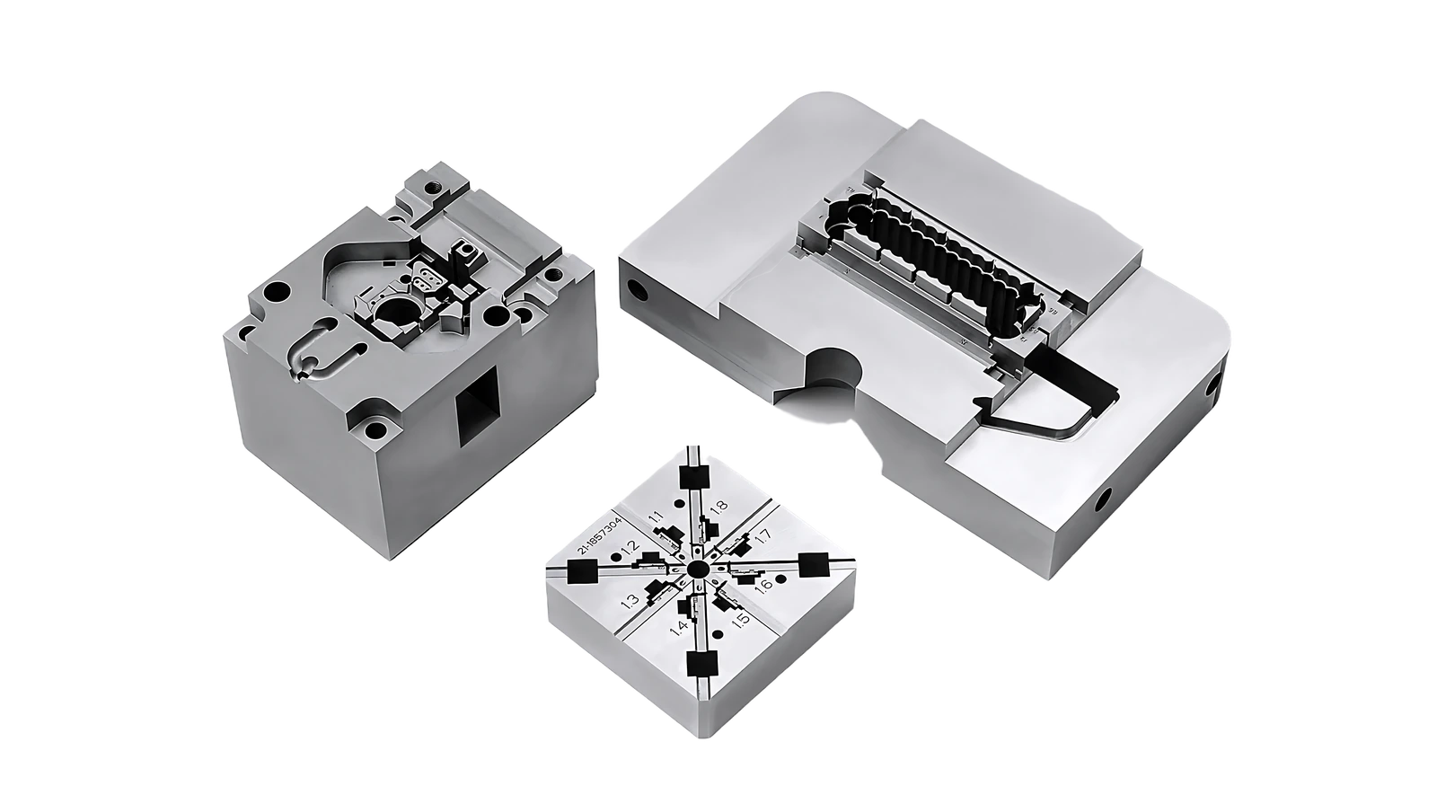
01 / Forming geometry, up close
Component geometry examples
CNC MILLING · EDM · GRINDING · INSPECTION
Precision follows the feature and the drawing.
01 / Component examples
Start with the shape.
Look closer at the detail.
Explore cavity and core geometry in component photographs. The drawing defines the function, material, fit and inspection requirements.
Cavity geometry ↓ Core geometry ↓
4 examples · select an image to enlarge
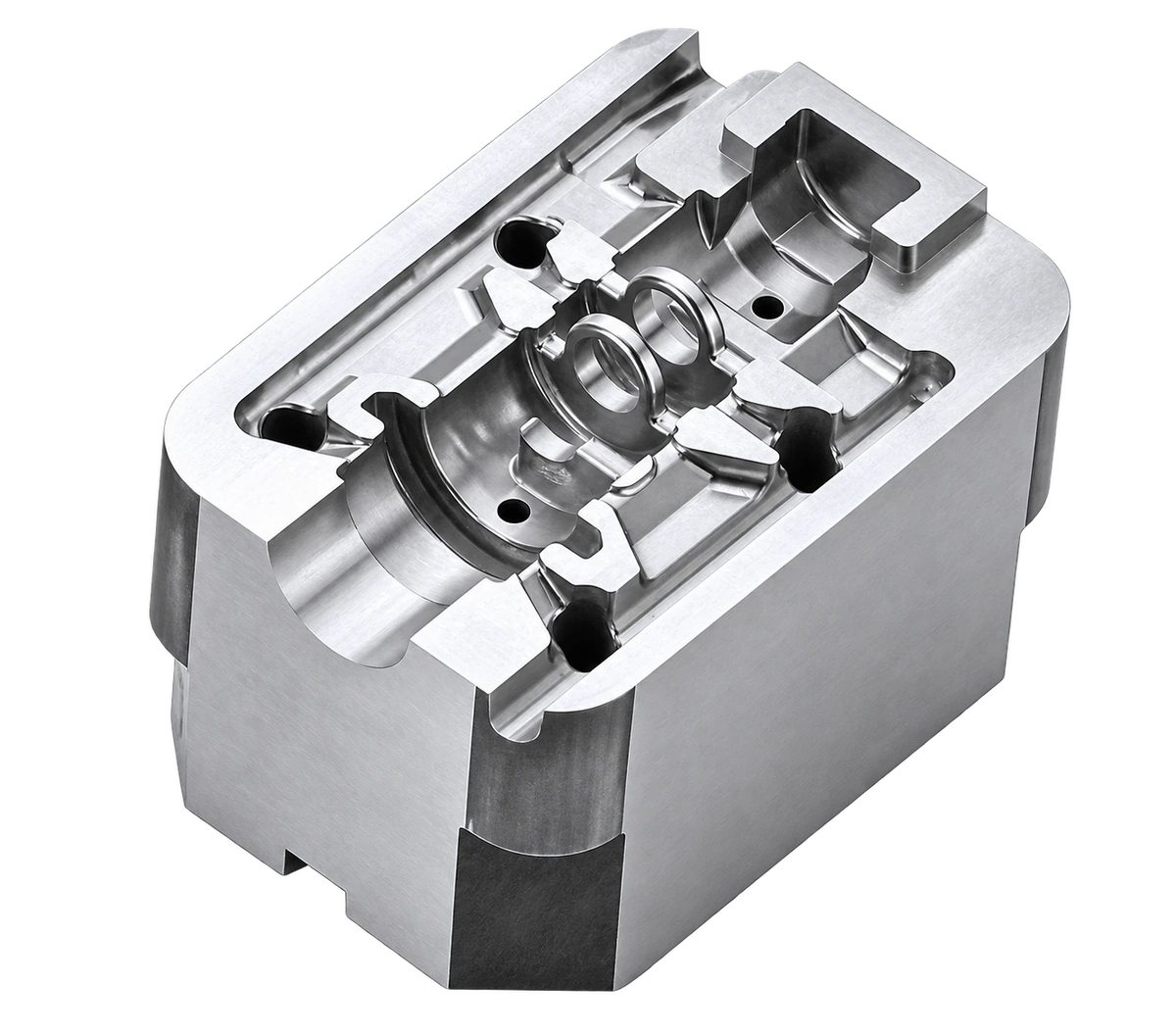
01 / Profiles & pockets
Contoured cavity geometry
Curved forming regions, local recesses and surrounding reference faces.
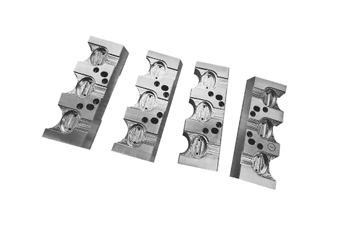
02 / Connected interfaces
Repeated forming details
A group of machined inserts with circular pockets and shared profile features.
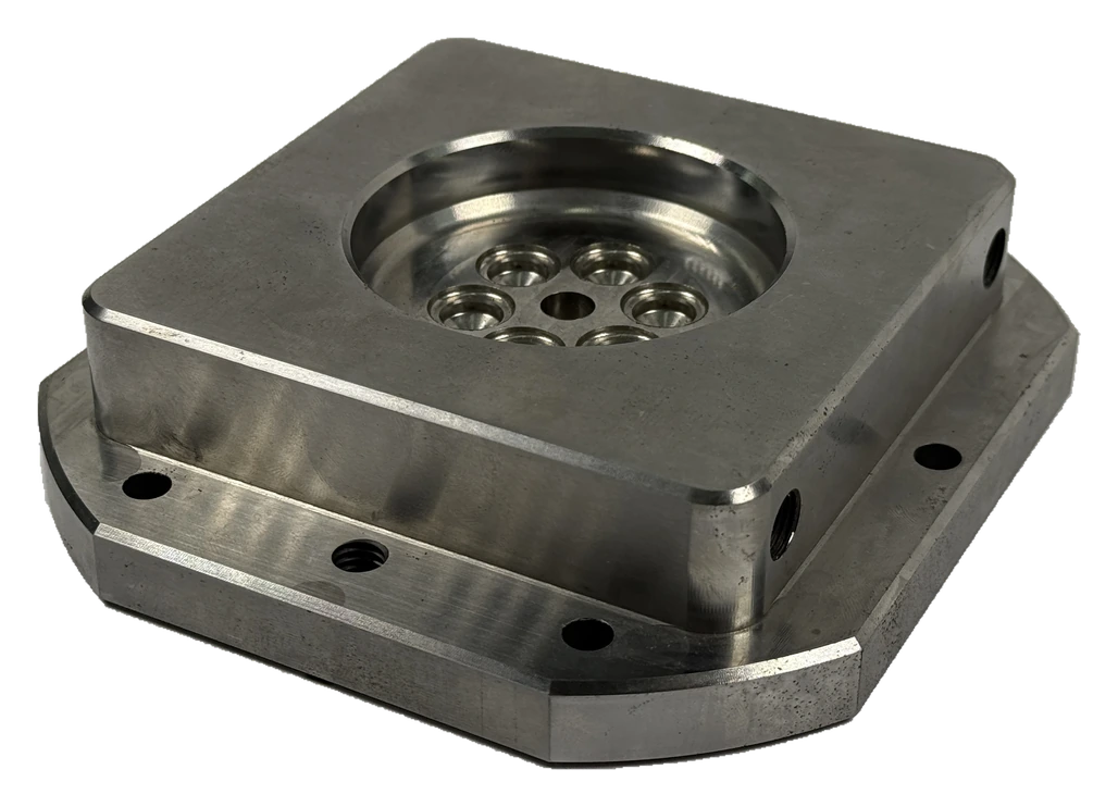
03 / Datums & access
Circular features in a block
Bores, holes and a recessed working region within a machined block.
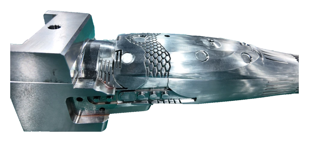
04 / Surface transitions
Detailed core geometry
A shaped core example with local contours and fine surface detail.
Product-library photographs. Open an image to inspect the visible geometry; functional dimensions follow the drawing.
02 / Function & fit
Three working surfaces.
One insert review.
Identify the surfaces that form the part, locate the insert and close the molding boundary. Mark the critical features in their assembly context.
Forming profiles and adjacent faces
Locating features and working geometry
For forming surfaces
Show the molded feature and finish zones.
Mark profiles, draft, ribs, radii and any appearance-critical areas.
For fitting surfaces
Provide the datum system and mating references.
Identify the seating faces, locating features and dimensions that control the insert position.
For shut-off surfaces
Show the contact geometry on both components.
Mark mating angles, boundary transitions and areas that must be evaluated after finishing.
Cavity inserts & core inserts: choosing the family
Start with the molded surface
A cavity insert generally forms external part surfaces. A core insert generally forms internal surfaces. The part geometry and mold layout define how the two work together; some inserts combine several forming and fitting functions.
For custom precision mold components, include the insert drawing and an assembly section when the working relationship is unclear. Identify which surfaces form the part and which features locate the component in the mold.
Replaceable inserts can support a local forming feature, maintenance requirement or tooling modification. Define the interface and drawing revision before the component is quoted.
Deep ribs, thin sections & machining access
Review the feature with its process access
Deep ribs, narrow slots and internal corners may require a combination of milling and EDM. Tool access, electrode geometry and required radii need to be considered together.
Thin steel sections and complex profiles require a sequence that accounts for rigidity, material condition and the specified heat treatment. Mark critical edges and areas where finishing could change a functional dimension.
Dimensions should describe what the feature must achieve in the mold. Avoid assigning one tolerance or one finish to every surface without reference to its role.
Datums, fitting dimensions & shut-off relationships
Provide the other side of the fit
Seating faces, locating bores, shoulders and mating profiles establish the insert position. State the datum system and identify the dimensions that control the relationship with the surrounding mold components.
For shut-off regions, show the contact geometry, angles and mating references. Specify where material condition, edge condition or finishing must be evaluated after processing.
Send the mating-component drawing or assembly view for replacement work. A component photograph alone cannot establish the required fit or acceptance criteria.
The drawing package: material, tolerance & finish
Keep the requirements connected
Include the current revision, 2D dimensions and available 3D model. List material grade, heat treatment, hardness and any coating requirements as specified for the insert.
Define critical dimensions, datums and surface finish by functional area. State requested measurement records and acceptance conditions at the quotation stage.
Manufacturing capability is reviewed against the geometry, finished material condition, access and inspection method. Final tolerances and surface requirements are confirmed from your drawing.
A useful starting package
Drawing & revision + Critical surfaces + Mating references + Finished condition
03 / From molded detail to everyday use
The small features
behind familiar products.
Use the finished part to explain what matters on the insert. Then connect that function to the mold drawing and its critical surfaces.

01 / Packaging & closures
A cap that closes.
Thread, sealing and tamper-band features can involve several forming components. Identify the insert surfaces that control the specified closure geometry.

02 / Electronics & connectors
A connector that fits.
Small ribs, terminal cavities and locating features need clear drawing references. Show the assembled connector when explaining the critical interface.

03 / Laboratory consumables
A sample transferred.
Hollow molded features and local transitions need to be reviewed with the part and mold design. Define the required finish, edges and inspection scope.
Typical use contexts. The part and mold drawings define the actual insert arrangement.
04 / Manufacturing & finished condition
Assign the process.
Keep the surfaces connected.
Milling, EDM and grinding can serve different features on the same insert. Plan the route around geometry, material condition and the finished requirements.
Machining & inspection references
Confirmed against your insert drawing.
01 / MACHINING
mm
Machining accuracy
Reference for suitable specified features, reviewed against geometry and finished material condition.
02 / SURFACE FINISH
Ra
µm
Surface roughness
Reference for designated surfaces. Define the finish zones, critical edges and acceptance method.
03 / INSPECTION
%
Piece-by-piece checks
Parts are checked individually. The measurement method and reported features follow the agreed scope.
Reference capability. Final precision, surface finish and inspection scope are confirmed against the drawing. Individual checks do not mean every feature is measured by CMM.
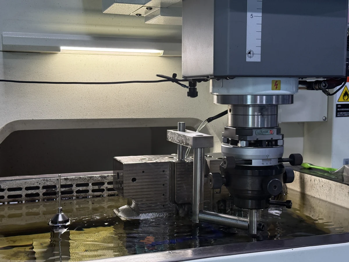
01 / Establish the geometry
CNC milling
Machine accessible profiles, pockets and reference features with the final sequence in mind.
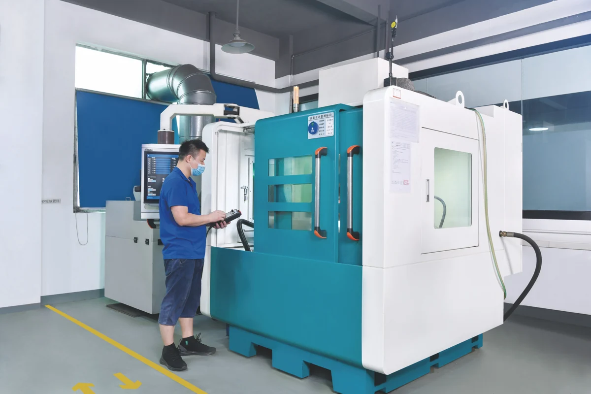
02 / Reach the detail
EDM & wire EDM
Review electrode access, slots and local geometry that need an electrical discharge process.
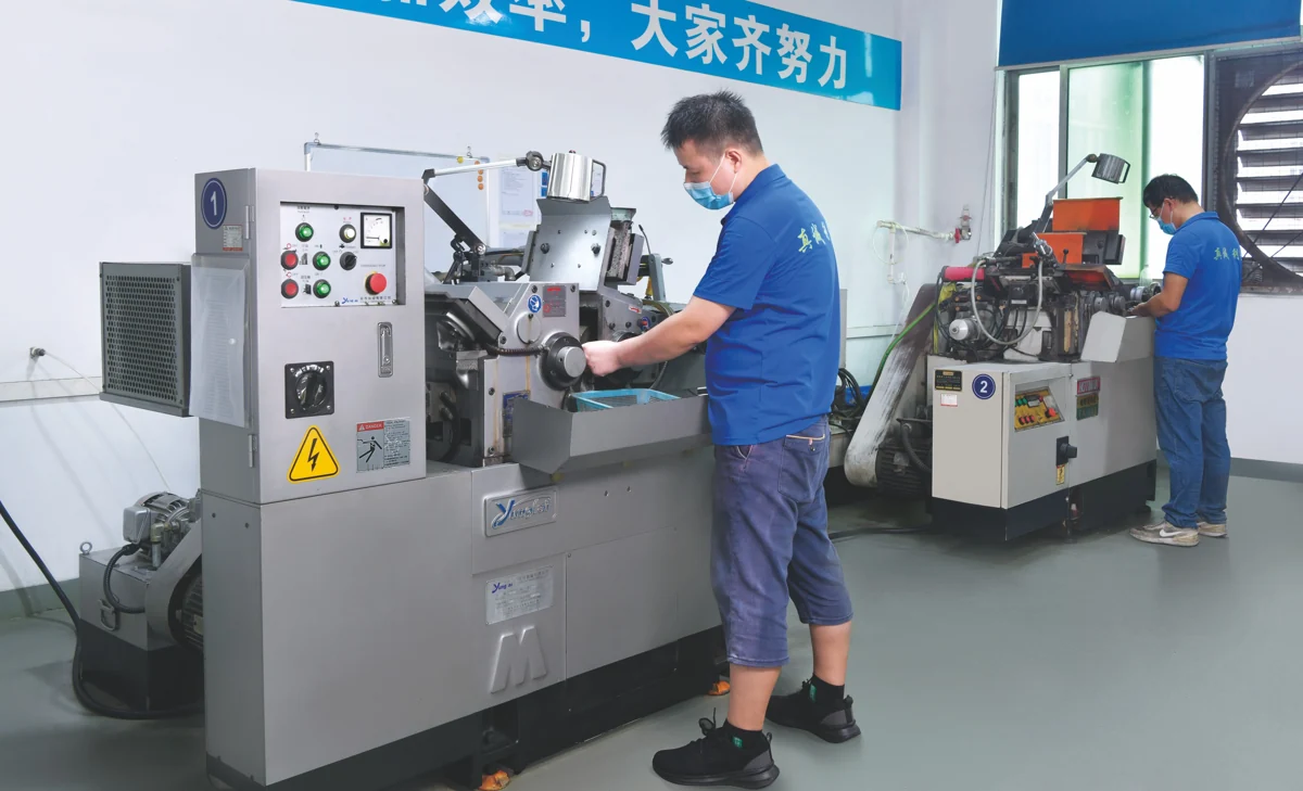
03 / Finish the fit
Grinding & finishing
Connect reference faces and critical dimensions to the specified finished condition.
Process sequence, heat treatment & allowances
Review the route for each insert
Rough machining, heat treatment, EDM, grinding and polishing can interact. Establish the material condition at each stage and identify any dimensions that need to be finished after treatment.
EDM electrodes, corner access and stock allowances should reflect the required geometry. Keep critical reference faces connected through the machining and measurement sequence.
External treatments and any additional reporting requirements belong in the agreed quotation scope. Sequence and delivery timing are confirmed for the specific drawing.
Material, hardness, coatings & finish zones
Specify the final condition
State the material grade and relevant specification, required hardness and heat-treatment condition. Identify any coating, texture or polishing requirements by surface.
Provide the intended use and mating context where they affect the review. Material or surface-treatment options should be evaluated against the project requirements rather than inferred from a component photograph.
Final hardness, finish and dimensional evidence must come from the corresponding order and inspection records. A requirement on a drawing is not itself a measured result.
Inspection / From datum to record
Check the feature.
Record what matters.
Agree the critical dimensions and acceptance references before production. The measuring method follows the feature, tolerance, access and datum system.
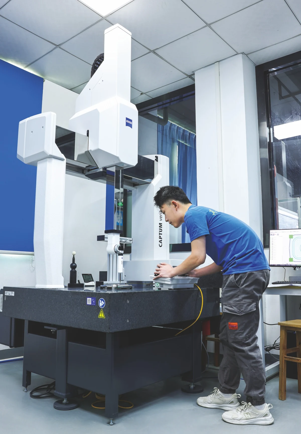
Datum relationships
Positions and profiles reviewed in the specified reference system.
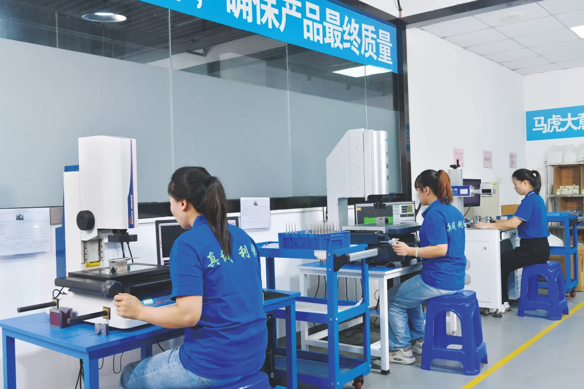
Fine profiles & edges
Accessible contours and fine details assessed with the appropriate method.
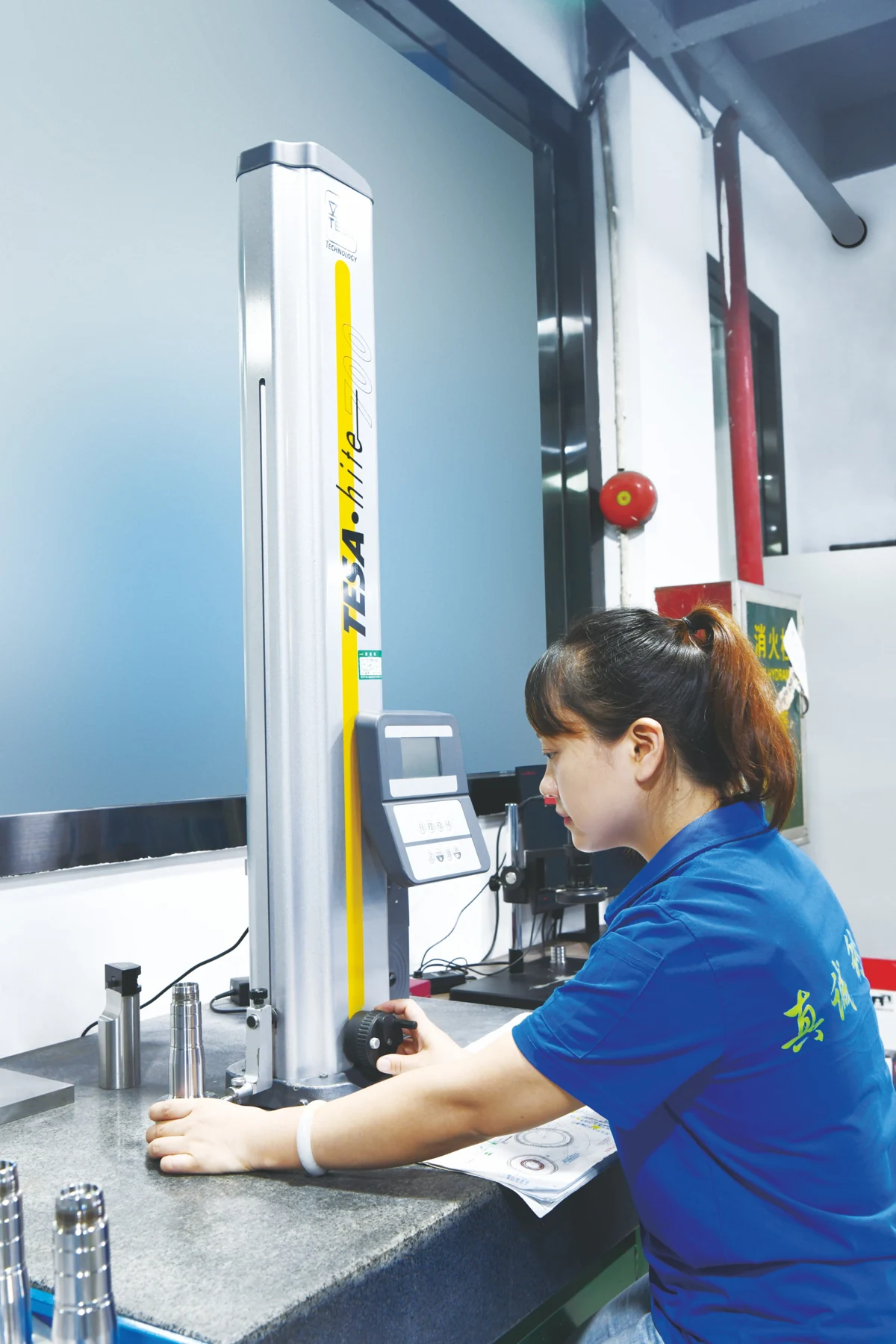
Steps & seating faces
Working heights and shoulders related to the agreed reference face.
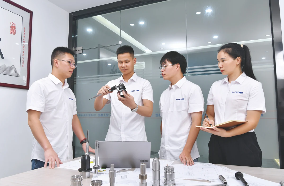
Review & records
Measurement requirements and requested results discussed by the technical team.
Critical features, measuring methods & records
Define the inspection scope at RFQ
Mark the forming profiles, fitting dimensions, datum references and shut-off features that require verification. State any requested dimensional reports, material records or surface checks.
CMM, optical measurement, gauges and other suitable methods are selected according to the feature and access. A general capability statement does not establish the method for every dimension.
Relate the recorded result to the drawing revision, measurement references and acceptance criteria. Discuss any features that need a mating or assembly reference before production starts.
Component inspection & mold-level acceptance
Keep the acceptance scope clear
Component inspection checks the agreed dimensions and characteristics. Mold assembly, shut-off contact, molding trials and the performance of the finished product require their own conditions and scope.
For replacement inserts, supply the existing assembly constraints and identify intended changes. Discuss how the component will be checked when the surrounding mold or mating parts are not supplied.
Workshop and inspection photographs show available activities; they do not establish a particular order’s measured results or customer acceptance.
Connected component families
Bring the other side
of the interface.
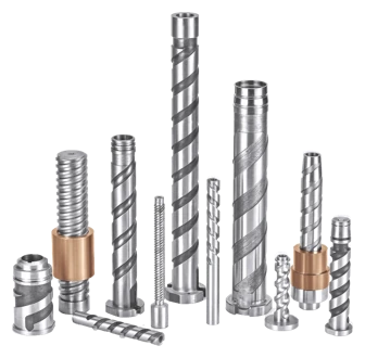
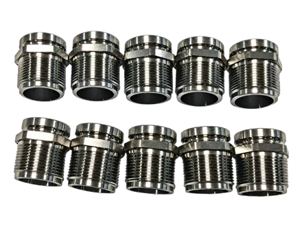
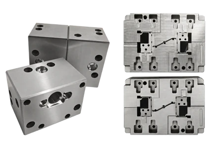
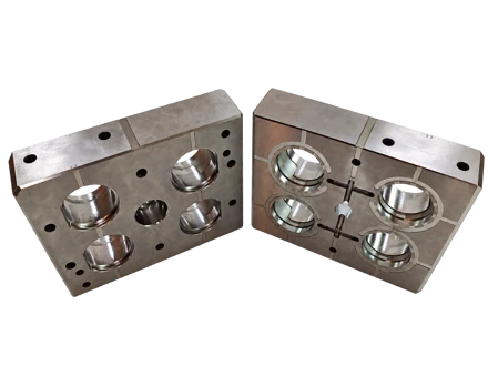
Send the related core, sleeve or moving component when it controls how the insert fits and works.
05 / Your project
Send the insert drawing.
Show what needs to work.
New tooling, a replacement or a local change—tell us what the component does and which requirements define acceptance.
Start with the current revision.
Include the component function, mating references, material and quantity.
Show the original fit and the wear.
Send the drawing, used-part photos and assembly references. Identify damaged areas and existing mold constraints.
Mark exactly what changes.
Supply the current and proposed revisions. Show how the change affects adjoining components and forming surfaces.
Connect the drawing, the fit and the requested records.
A focused mold insert RFQ
The drawing.
The interface.
The finished condition.
- 2D drawing, available 3D model & revision
- Critical profiles, datums & mating references
- Material, heat treatment & surface requirements
- Quantity, target date & required inspection records
No drawing ready? Start with a description. Request an NDA before sharing restricted files.
Confirm the drawing revision, critical surfaces, material and requested checks.
Agree the process route, finished condition, treatment scope and proposed timing.
Review the agreed inspection records, part identification and protection before dispatch.
Replacement inserts, wear & existing mold constraints
Separate the original specification from wear
Provide the current drawing revision, used-part photographs and the original fit requirements when available. Identify damaged areas, mating dimensions and assembly constraints.
Mark the exact changes for a modification. Supply both existing and proposed revisions so the effect on adjacent parts, forming surfaces and inspection can be reviewed.
When only a worn sample is available, discuss the available design information and measurement references. The worn geometry alone may not establish the original design intent.
Common drawing review questions
Can one insert need milling, EDM and grinding?
Yes. Different features can require different processes. Geometry, access, material condition and final requirements determine the proposed sequence.
What precision can you confirm?
Precision is confirmed against the specified drawing features and acceptance method. The capability references above are a starting point for that review.
What should I send without a complete drawing?
Share the function, known dimensions, photographs and mating context. Identify any missing information and whether an NDA is needed before more detail can be supplied.
Can I request inspection documents?
Include the required record types and critical characteristics at RFQ so the quotation can account for them.