Products / Made to your drawing
SENLAN PRECISION DONGGUAN, CHINA
Custom precision
mold components.
An extension of
your toolroom.
From a critical insert to a replacement core. We manufacture custom mold parts to your 2D and 3D drawings, with the fit, material and inspection requirements reviewed together.
For moldmakers, tooling engineers and in-house toolrooms.
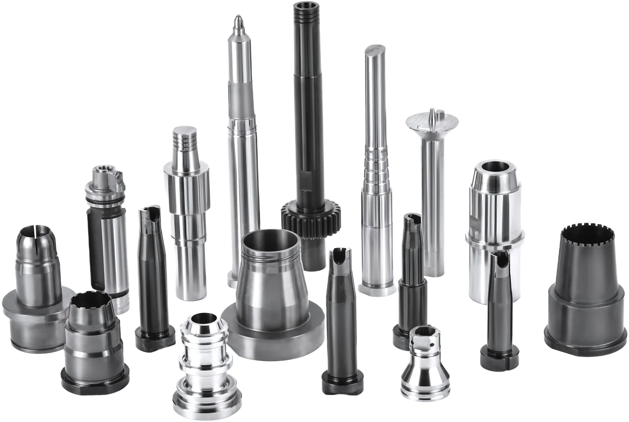
01New mold projectsCustom forming and fitting parts
02Complex geometryCoordinated CNC, EDM and grinding
03Replacement & repeat partsOriginal drawings and mating references
01 / Product families
Find the component
your mold needs.
Start with the part’s function. Explore the geometry, mating features and manufacturing considerations within each family.
Choose by function
+
No standard part name?
Start with your drawing.
01
FORMING SURFACES
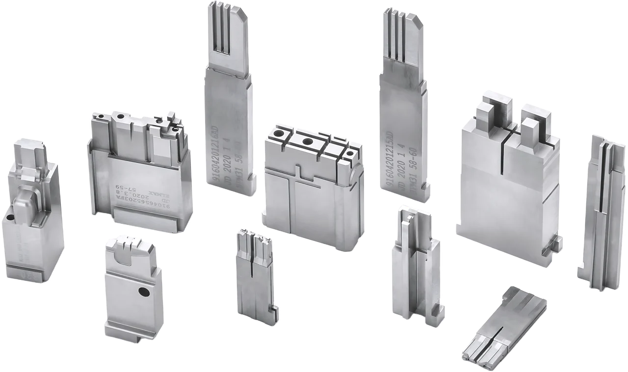
Precision Mold Inserts
Core and cavity inserts that define molded surfaces, shut-offs and locating features.
Cavity inserts · Core inserts · Mold cores
Review: Forming profile, datums and mating fit.
02
INTERNAL & THREADED FEATURES
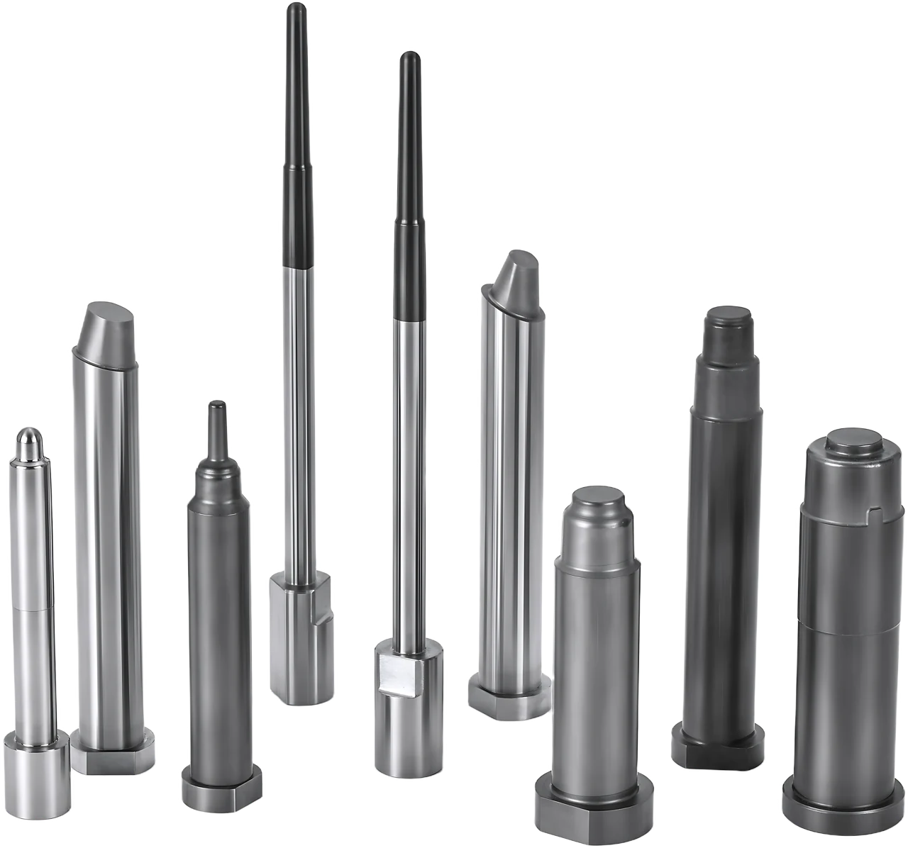
Core & Forming Components
Core pins and forming components for holes, internal geometry, threads and closure details.
Core pins · Thread cores · Neck ring components
Review: Working length, concentricity and finish.
03
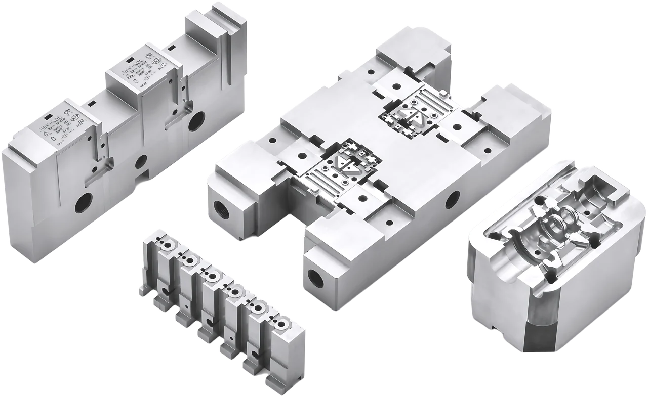
MOVING INTERFACES & INTRICATE FEATURES
Complex Mold Components
Sliders, lifter inserts and complex parts for undercuts, movement and irregular forming geometry.
Sliders · Lifter inserts · Collapsible core components
Review: Shut-offs, travel interfaces and assembly.
04
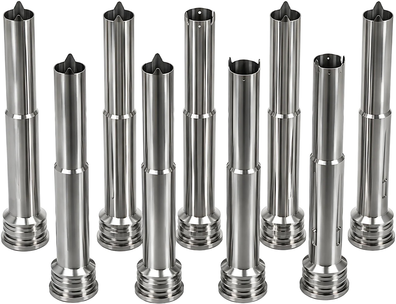
GUIDING, FORMING & EJECTION
Sleeve Components
Precision sleeves for controlled ID/OD relationships, sliding fits and ejection functions.
Ejector sleeves · Core sleeves
Review: Bore, wall thickness and working clearance.
05
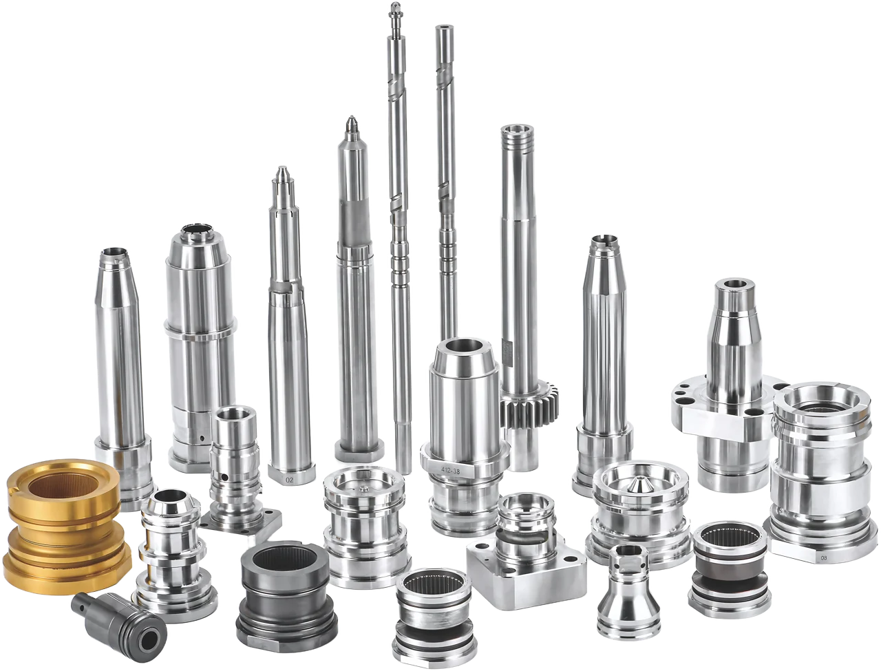
SPECIAL & REPLACEMENT PARTS
Precision Plastic Mold Components
Other drawing-based injection mold components, special inserts and replacement parts.
Special geometry · Repair parts · Repeat orders
Review: Part function, original geometry and revision.
02 / The details that matter
A part has to do
more than
match a dimension.
Show us how it fits, forms or moves. These relationships help define the machining route and the checks to agree before production.
01
Fit with the mating part
Identify locating faces, datums, clearances and the components that work together.
BORES / SHOULDERS / SLIDING SURFACES
02
Form the intended detail
Flag deep ribs, thin steel, long slender features and surface requirements that affect access or finishing.
DEEP FEATURES / THREADS / COMPLEX PROFILES
03
Match the original requirement
For replacement parts, distinguish the intended geometry from wear, repairs and later modifications.
DRAWING REVISION / MATING REFERENCE / REPEAT ORDER
03 / From drawing to component
Your geometry.
A coordinated process.
CNC machining, EDM and precision grinding are selected around the part’s features, material condition and inspection access.
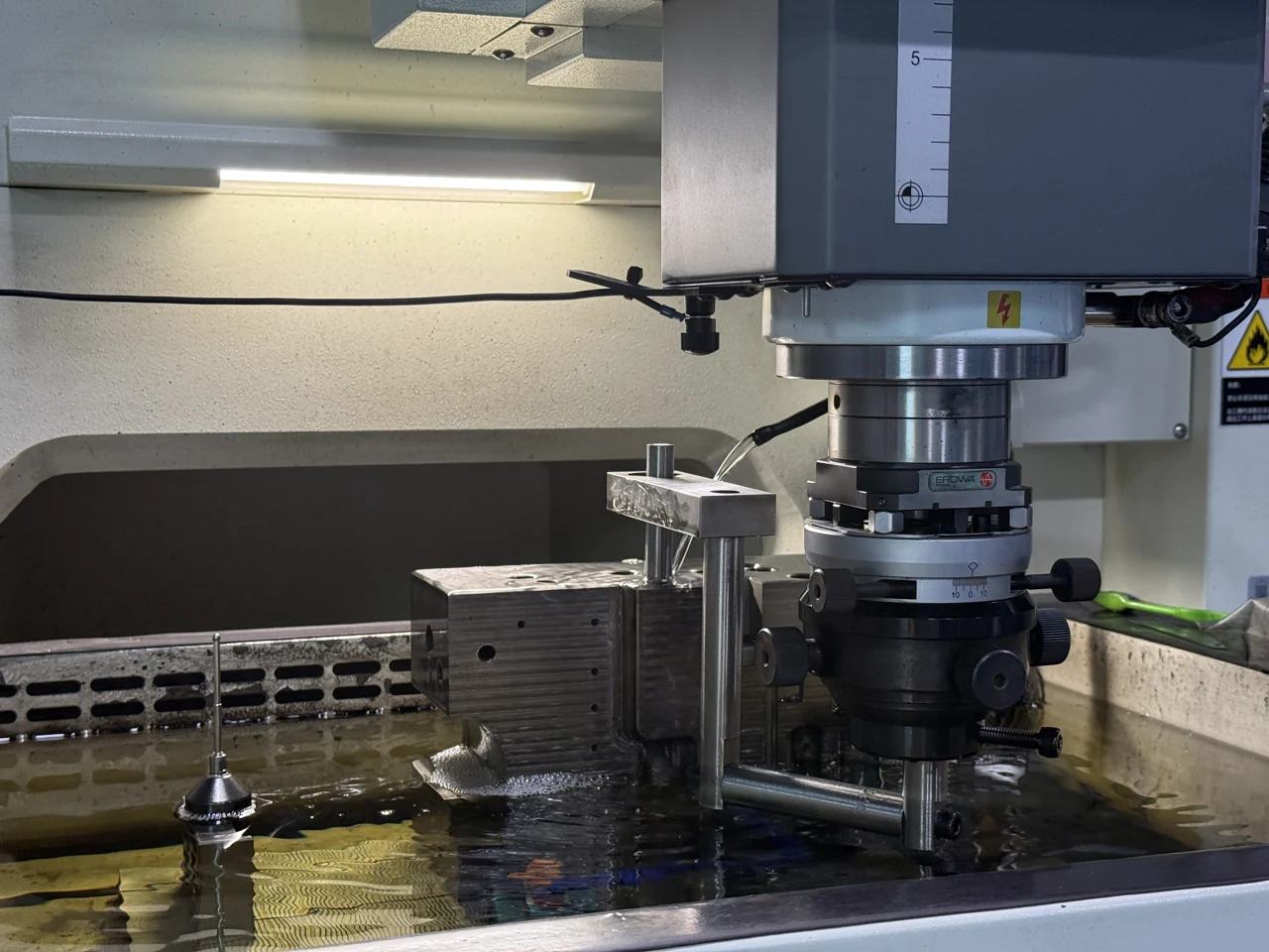
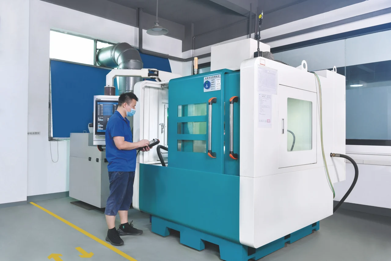
CNC MACHINING
01 / Establish the geometry
CNC milling & turning
Primary surfaces, bores, steps and profiles. Establish datums and plan finishing allowances.
EDM & WIRE EDM
02 / Reach the detail
EDM & wire EDM
Deep ribs, narrow details and intricate contours. Review electrode or wire access.
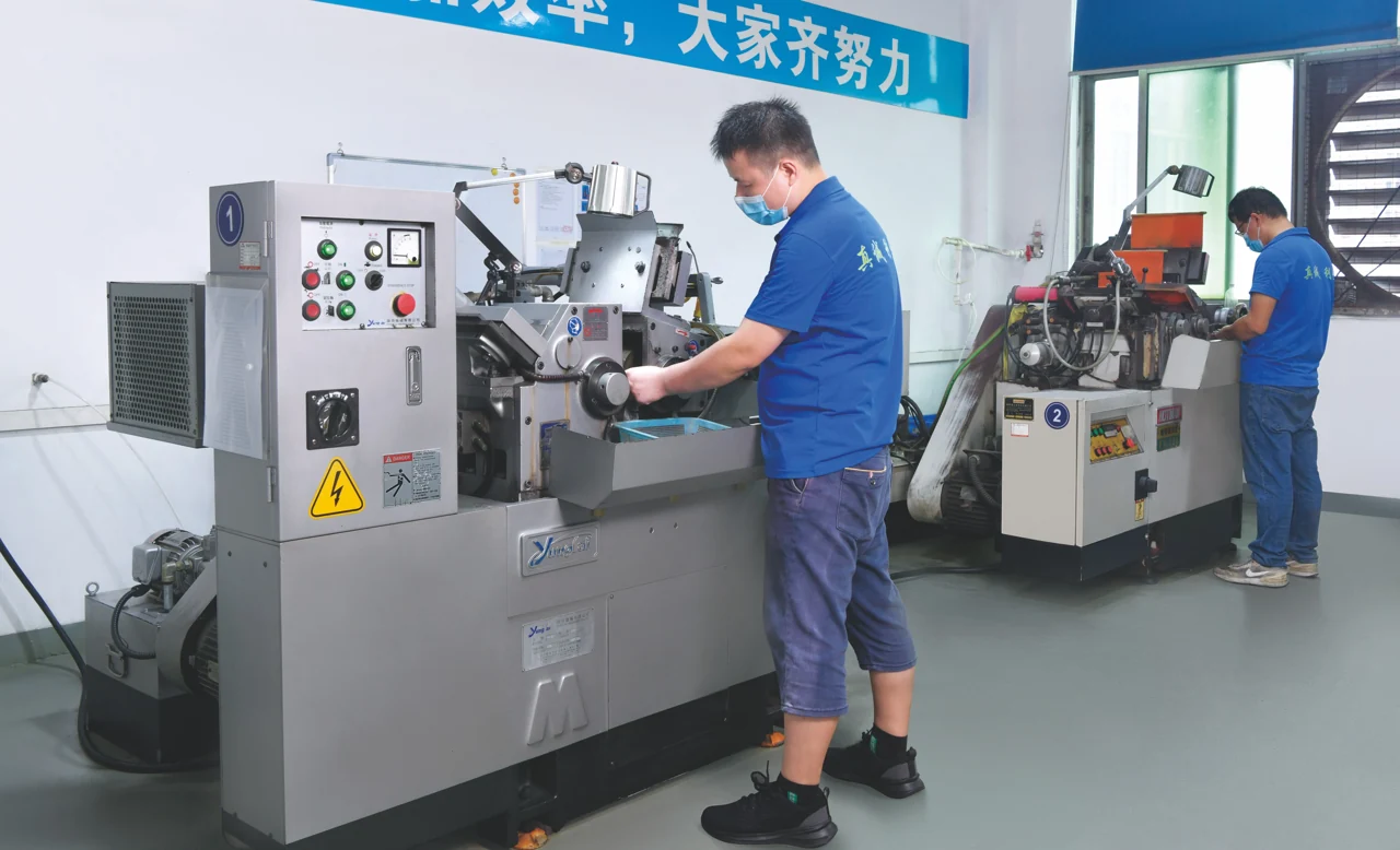
PRECISION GRINDING
03 / Finish the relationship
Grinding & finishing
Functional diameters, faces and profiles. Finish to the agreed material condition and fit.
Material and finish belong in the brief.
Specify the grade, source, hardness, heat treatment and surface requirements when you send the drawing.
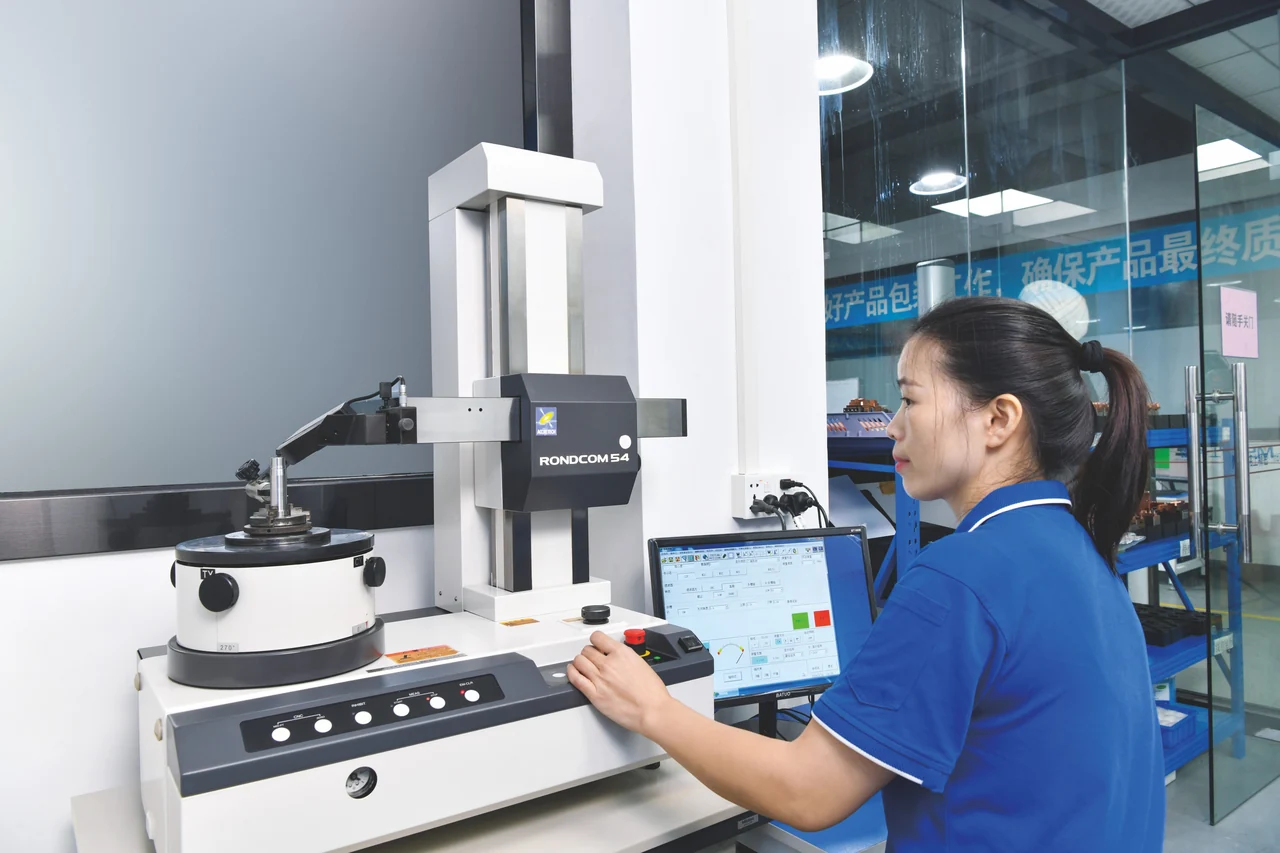
AT THE INSPECTION BENCHRoundness inspection
THE DRAWING SETS THE CHECK.
+
Inspection & traceability
Make the critical
features measurable.
Define what needs to be verified before the part is made. Inspection methods and records follow the agreed feature requirements.
01
Functional dimensions
Identify the datum scheme, fit dimensions, concentric relationships and profiles to check.
02
Specified material condition
Confirm material, heat treatment and finish requirements, with traceability documents agreed at quotation.
03
Inspection records
Define report scope and critical dimensions so your receiving team knows what to review.
Components in context
Different molds.
Shared attention to detail.
Application context helps explain the part’s function. The drawing defines the manufacturing scope.
01 / ELECTRONICS
Electronics &
connector molds
Fine forming details, dense cavities and matched interfaces.
↗
03 / PACKAGING
Packaging &
closure molds
Thread forms, sealing details and core–cavity relationships.
↗
Working on another mold application? Send the component drawing
Do you manufacture custom or standard mold parts?
Our focus is drawing-based, non-standard precision mold components. We review geometry, material, quantity, critical features and inspection requirements before confirming the manufacturing scope.
Can you make replacement parts for an existing mold?
Yes. Share the original drawing, revision and mating-part information where available. Identify any wear, repairs or modifications so the intended geometry and fit can be reviewed.
What if my part does not fit one product category?
Start with Precision Plastic Mold Components or send the drawing directly. Include the component’s function and assembly context. A standard product name is not required.
How are tolerances and delivery dates confirmed?
They are reviewed for the specific drawing, material condition, process route and quantity. Mark critical requirements and your target delivery date in the RFQ so feasibility and timing can be agreed for the project.
04 / Your next component
Bring the drawing.
Let’s review the part.
A new project, a complex detail or a replacement.
Start with the files you have.
FROM 2D TO 3D
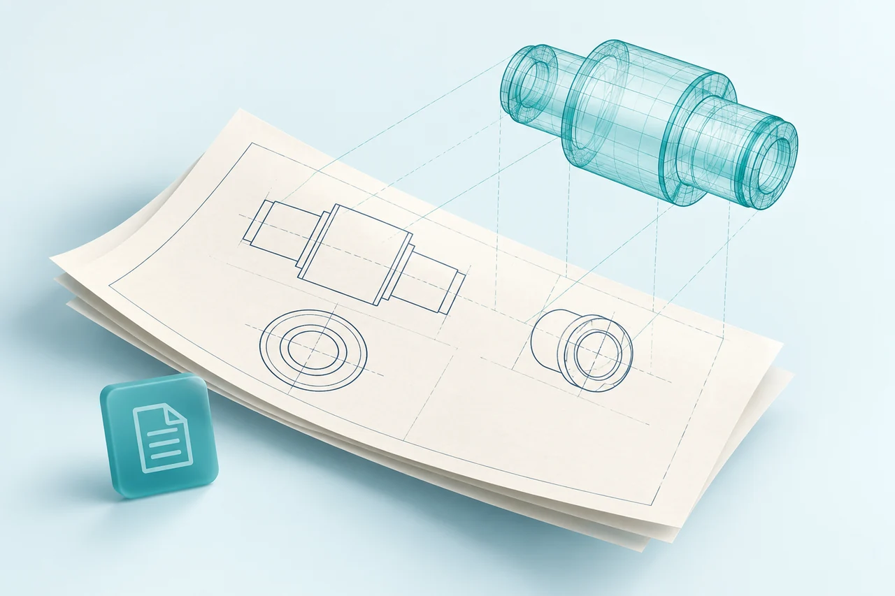
AI-generated drawing concept · Not a production drawing.
A useful manufacturing brief
01
Your 2D / 3D files
Current revision, quantity and target delivery date.
02
The finished condition
Material, hardness, heat treatment and surface finish.
03
What matters in assembly
Critical dimensions, datums, mating parts and required inspection records.
Have a technical question? Contact us
Drawing review → Technical clarification → Project quotation