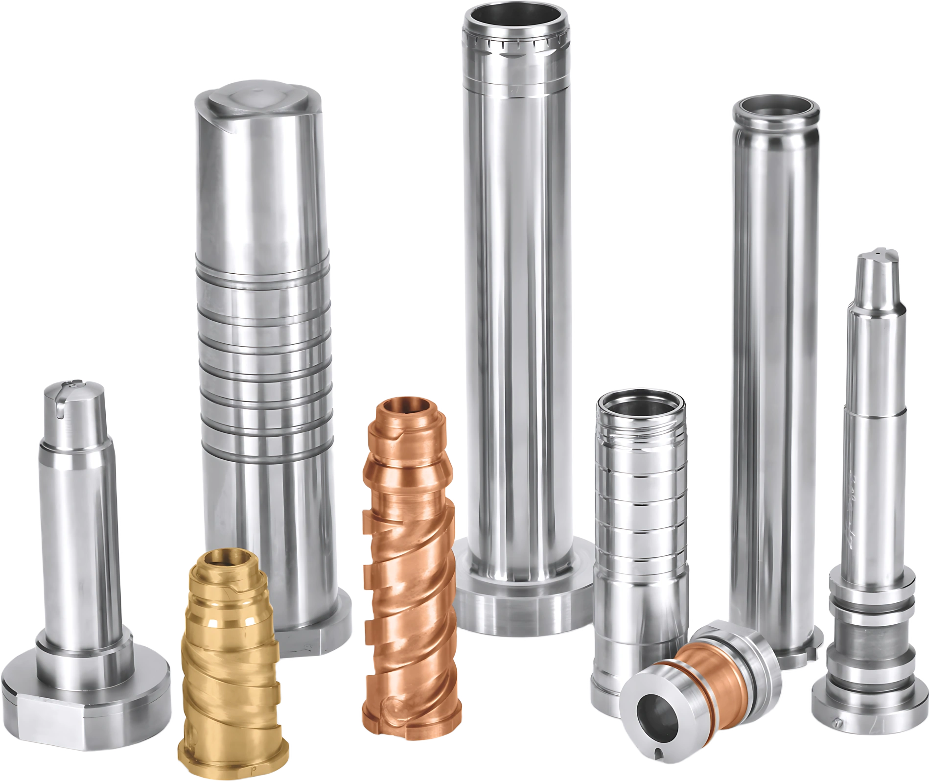
SURFACE, CYLINDRICAL & INTERNAL GRINDING
Precision grinding.
For mold components.
Focused on the fit.
Final dimensions. Fitting surfaces.
Defined datum relationships.
Bring the surfaces that determine fit into one grinding plan, reviewed around your drawing, material condition and inspection requirements.
Drawing review · Grinding route · Feature inspection
01 / GRINDING EQUIPMENT
The right setup.
A defined grinding route.
Surface, cylindrical and centerless grinding serve different features. We review the part envelope, holding and wheel access around your drawing.
CYLINDRICAL GRINDING
Ø400
Diameter
max. / mm
CYLINDRICAL GRINDING
1000
Length
max. / mm
SURFACE GRINDING
300
Length
max. / mm
SURFACE GRINDING
150
Width
max. / mm
Recorded grinding process ranges in mm, not individual machine-axis travel. Final feasibility depends on geometry, holding and the agreed grinding route.
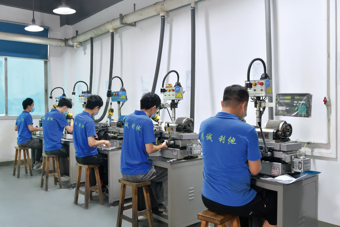
Inside the grinding workshop.
Hover or tap to explore
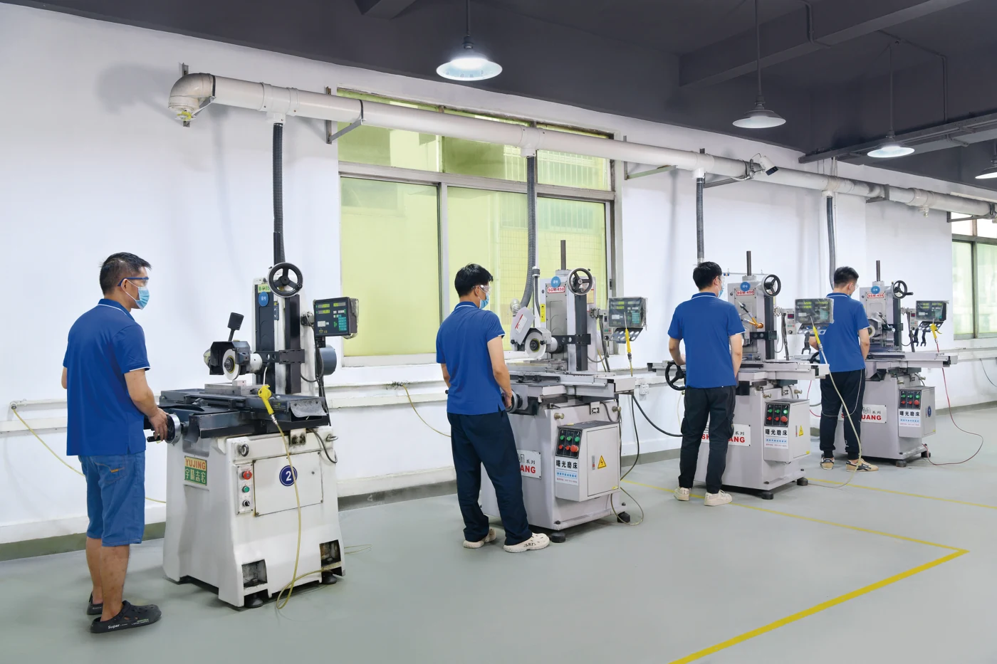
7 units
Faces, steps & thicknessPrecision surface grinding+
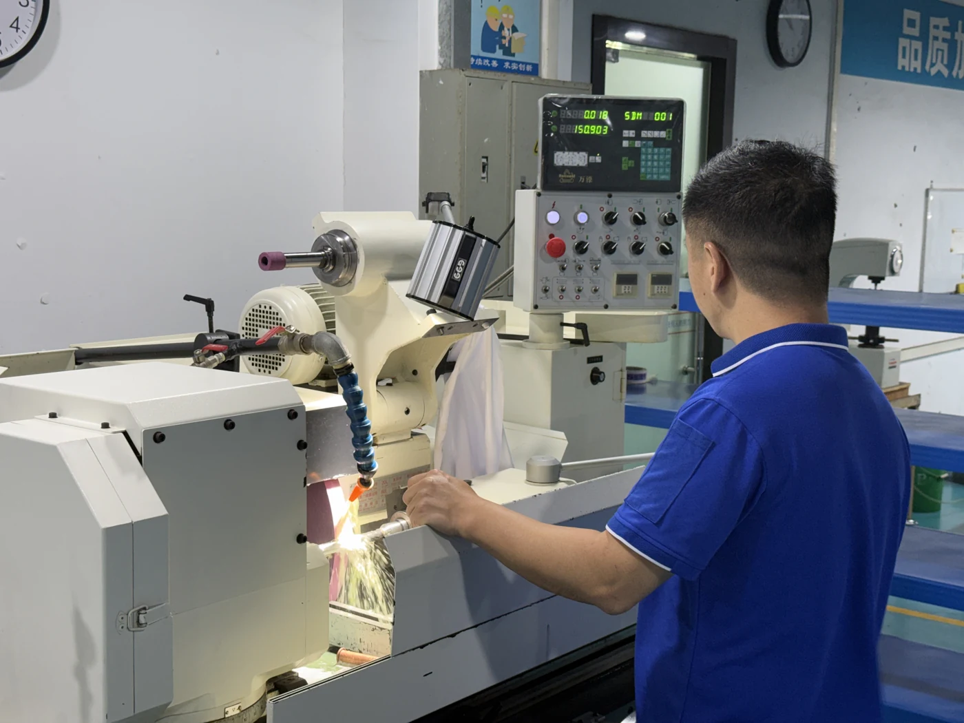
CYLINDRICAL
Bores, ODs & shouldersOD / ID grinding+
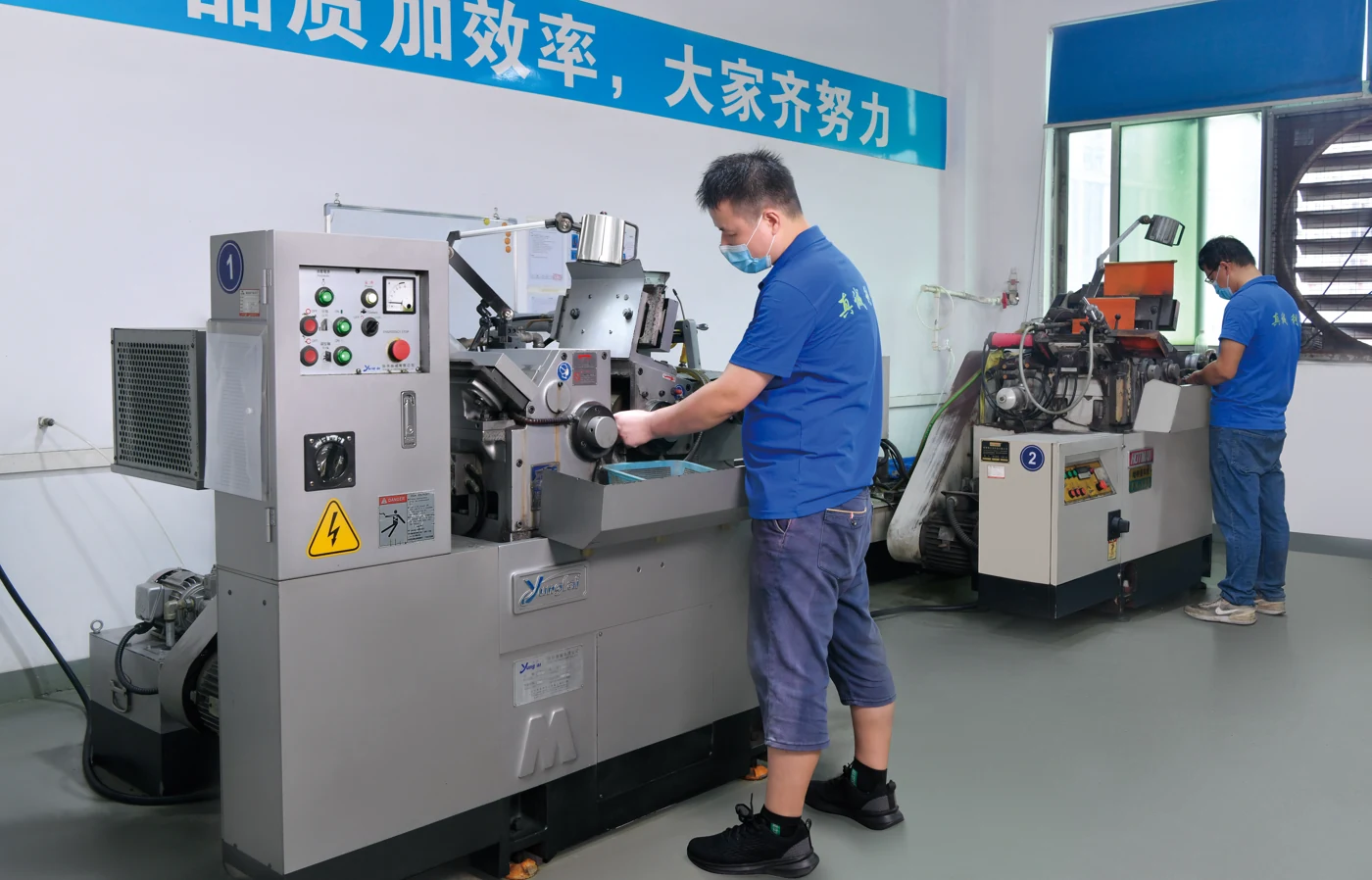
ROUND PARTS
Suitable cylindrical geometryCenterless grinding+
5 units
Small round & formed featuresPunch forming & grinding+

SURFACE WORK
Larger planes & reference facesLarge surface grinding+
THE COMPLETE MANUFACTURING PICTURE
Manufacturing & Quality ↗
Materials, process planning and inspection resources.
02 / FEATURES & PROCESS
The fit is in
the relationships.
Review the surfaces that have to work together, the condition in which the part arrives and how the finished features will be checked.
Compare grinding routes and drawing inputs.
| Route | Typical feature | Drawing input |
|---|---|---|
| Surface | Seating faces, thickness, steps and fitting planes. | Drawing input: Datums, thickness limits, flatness and orientation. |
| OD / cylindrical | External diameters and stepped cylindrical fits. | Drawing input: Diameter zones, reference axis, shoulders and reliefs. |
| ID / internal | Accessible bores and internal fitting surfaces. | Drawing input: Bore size and depth, wall support and OD relationship. |
| Centerless | Suitable pin and shaft external diameters. | Drawing input: Diameter, straightness and supportable geometry. |
| Punch forming | Selected small round and formed features. | Drawing input: Profile, transitions, access and inspection references. |
01 / PLANES & HEIGHTS
Control the reference.
Then finish the face.
The seating face, side references and working face need a common datum plan. Treat thickness, flatness, parallelism and squareness as separate requirements.
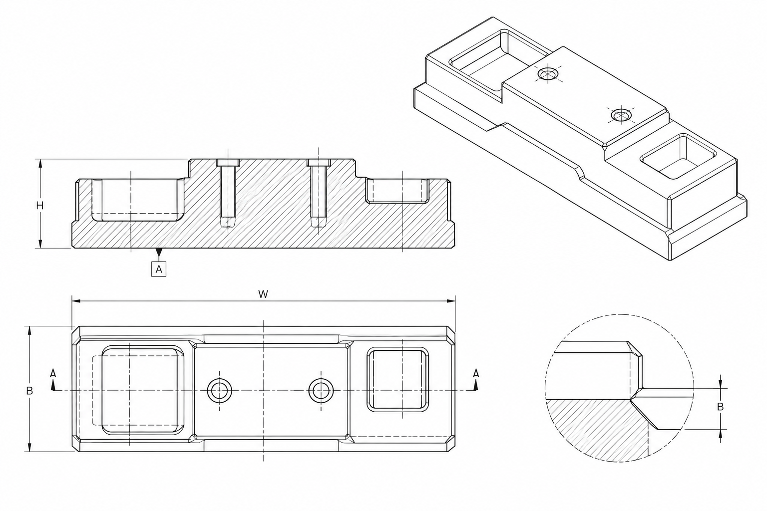
Start with the functional datum.
Mark the seating face, side references and final working face. State which relationship matters to assembly, rather than relying on a thickness dimension to describe every face.
Separate size, form and orientation.
Thickness, flatness, parallelism and squareness answer different questions. A thickness reading alone does not establish the form or orientation of all six faces.
Define how matched heights are compared.
For matched heights, identify the common reference, measurement locations and comparison method. Include the associated mating or assembly requirements.
DEFINE
Datums & working faces
CONTROL
Thickness, form & orientation
CHECK
Common reference & method
02 / DIAMETERS & AXES
A fitting diameter.
A defined relationship.
Define the datum axis and the relationship between the bore, OD and shoulder. Roundness, cylindricity and runout answer different questions; specify the checks your assembly needs.
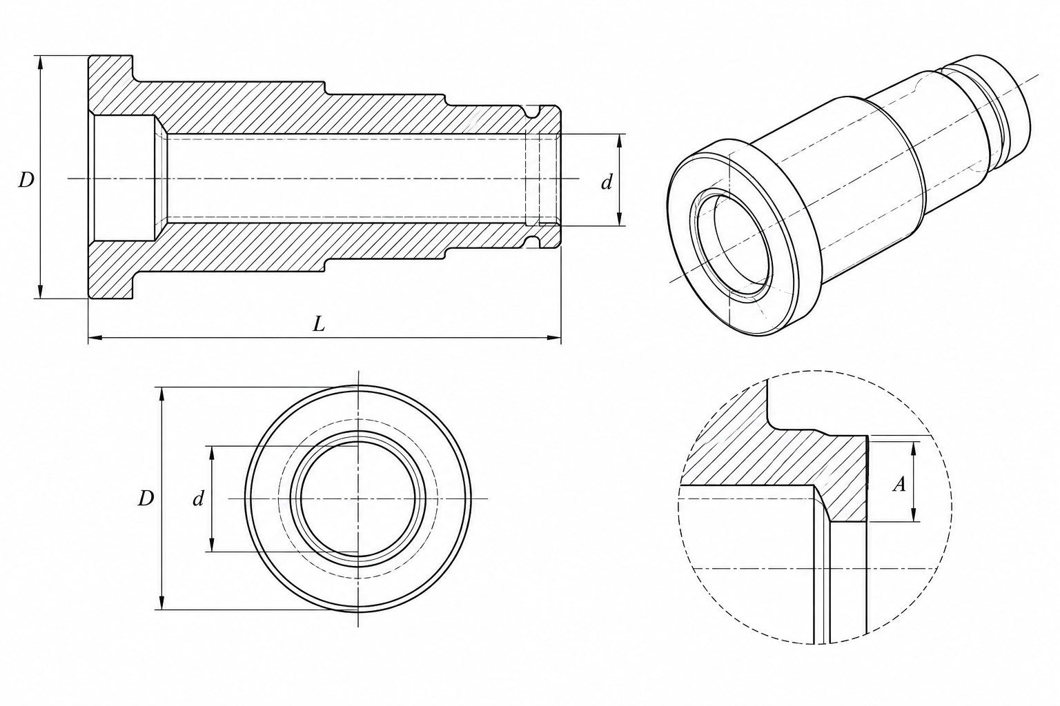
OD grinding: connect the fit to its axis.
For external diameters and stepped cylindrical fits, identify the diameter zones, reference axis, shoulders and reliefs. Include the faces used to locate or seat the component.
ID grinding: review access and support.
For accessible bores and internal fitting surfaces, provide the bore size and depth, wall support and relationship to the OD. Bore depth, shoulders and thin walls influence wheel access and holding.
Agree on the checks that describe the fit.
Do not substitute one axis or form check for another. Include a section view, protected clamping areas and mating-part information so the inspection scope can be matched to the drawing.
LOCATE
Datum axis & shoulder
REVIEW
Wheel access & wall support
VERIFY
Size, form & axis relationship
03 / ROUND & FORMED FEATURES
Match the route
to the geometry.
Small round parts need a review of feeding, support, transitions and access. The process name alone does not define the acceptance scope.
CENTERLESS
Support the cylindrical geometry.
Centerless grinding supports suitable cylindrical geometry without holding the part between centers. Shoulders, interrupted sections and slender parts need a review of feeding, support and straightness.
PUNCH FORMING
Review the selected feature.
The equipment record includes punch forming and grinding for selected small round and formed features. Share the profile, transitions, access and inspection references needed to review the route.
METHOD REVIEW
Define complex profiles separately.
Optical PG, complex profile grinding and jig grinding require a separate method review. Share the geometry and acceptance requirements so the proposed scope can be confirmed.
GEOMETRY
Diameter, steps & transitions
SUPPORT
Feeding, holding & access
AGREE
Method & acceptance scope
04 / CONTROL THE HANDOFF
Plan the last cut.
Check what matters.
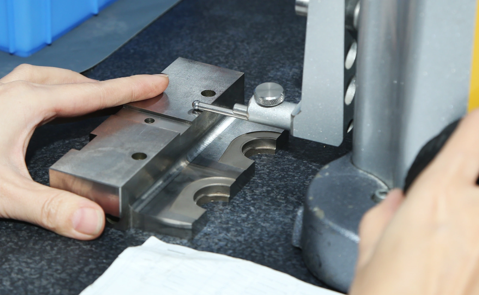
The incoming part condition matters as much as the finished feature. Agree on allowance, holding and inspection before the last material is removed.
Stock & material condition
Specify the material, heat-treatment stage and previous machining. State where stock remains and whether the allowance is per side or overall.
Holding & support
Identify seating and locating surfaces, protected areas and support for thin or slender sections. Maintain the intended datum relationship between operations.
Heat & surface condition
Review grinding passes, wheel condition and cooling. Define any checks for burns, cracks, edge damage or other surface risks and their acceptance methods.
Inspection & reporting
Map critical features to size, form, axis or surface checks. Agree on measurement locations, coverage and any individual matching or reporting requirements.
INCOMING
Material, condition & stock
PROCESS
Holding, cooling & reference
REPORT
Features, method & revision
Have a critical face, a fitting diameter or a matched set?
Explore by component.
Choose the geometry closest to your drawing.
03 / DRAWING REVIEW
Share the surfaces
that control the fit.
For moldmakers and in-house toolrooms: new components, replacements or repeat work. Mark the faces, diameters and relationships that determine fit.
Include with your drawing:
01
Drawing & critical features
Current revision, units, datums, final dimensions and mating requirements.
02
Material & incoming condition
Grade, heat-treatment state, allowance and protected features.
03
Quantity & inspection
Quantity, matching requirements, measurement scope and required reports.
We review the scope before confirming feasibility and quotation.
Before you send a drawingQuotation questions +
What should I send for a grinding quotation?
Send the current drawing and revision, material and condition, quantity, incoming stock and the features that determine fit. Include inspection, matching and documentation requirements.
Can you confirm a tolerance before reviewing the part?
Feasibility depends on feature size, material condition, holding, access, finishing route and measurement method. Mark the critical requirements so the review addresses the actual component.
How are small profiles and special grinding methods reviewed?
Share the complete profile, transitions, access and acceptance requirements. Optical PG, complex profile and jig grinding need a separate method review before the route and completed scope can be confirmed.