

SINKER EDM & WIRE EDM
EDM & Wire EDM.
Reach the detail.
Keep the reference.
For blind cavities, local internal forms and through contours in precision mold components. Reviewed around your drawing, material, datums and surface requirements.
Drawing review · Process routing · Feature inspection
SENLAN / EDM work area · existing library photograph
01 / MACHINING RANGES & EQUIPMENT
Room for the feature.
Focus on the detail.
Start with the recorded machining range, then review the machine, workholding and electrode approach around your drawing. Blind forms and through profiles need different access.
Recorded machining ranges
Maximum process range · mm
SINKER EDM
Length
500
Width
500
Height
400
WIRE EDM
Length
1500
Width
1000
Height
1000
These are recorded process-capacity limits, not individual machine-axis travel. Feasibility depends on the part geometry, material, fixtures and access.
Sinker EDM equipment
Equipment images and manufacturer axis-travel references
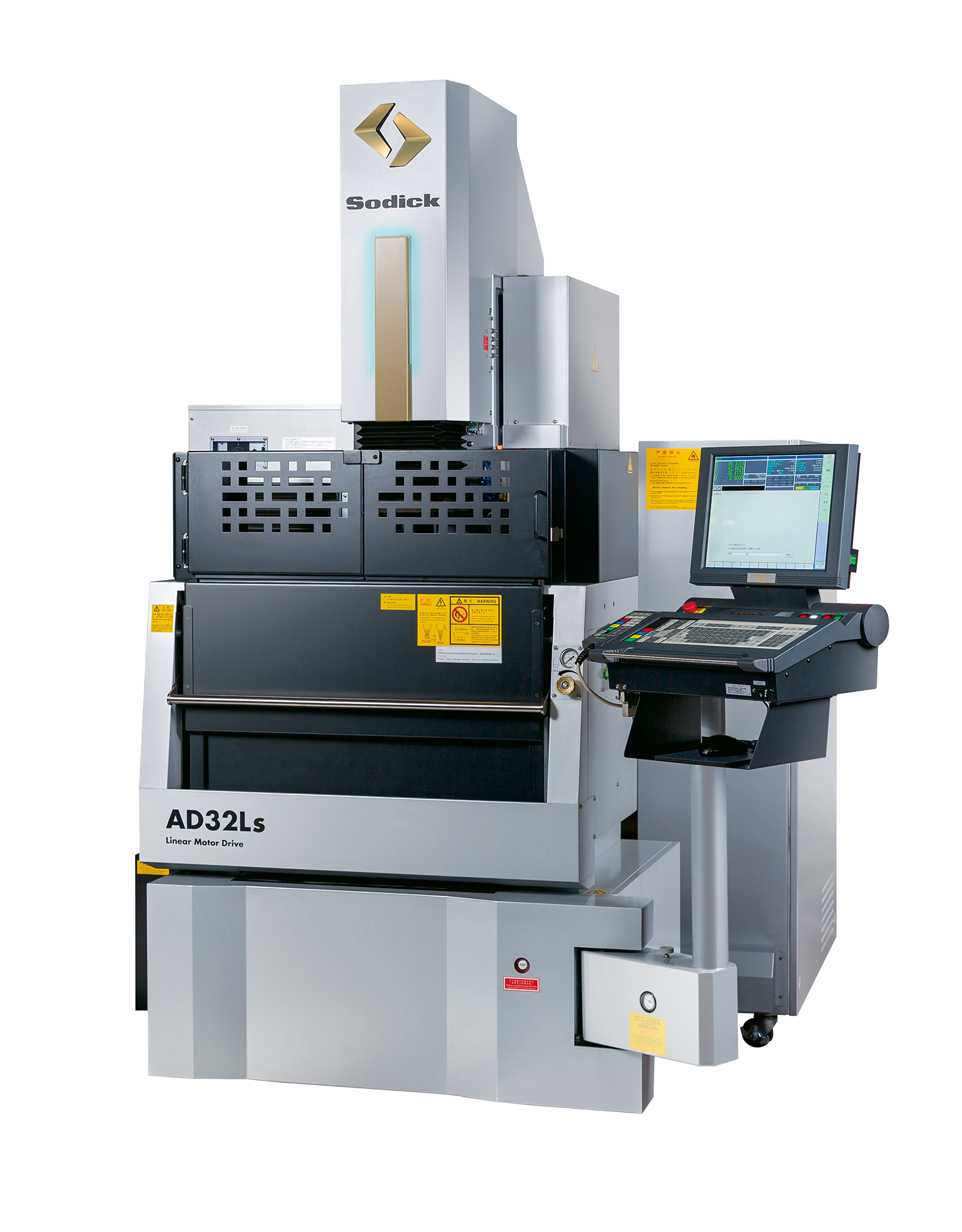
SINKER EDM
5 units
SODICK
AD32Ls
X / Y / Z axis travel mm
X
330
Y
220
Z
250
Manufacturer image · AD32Ls
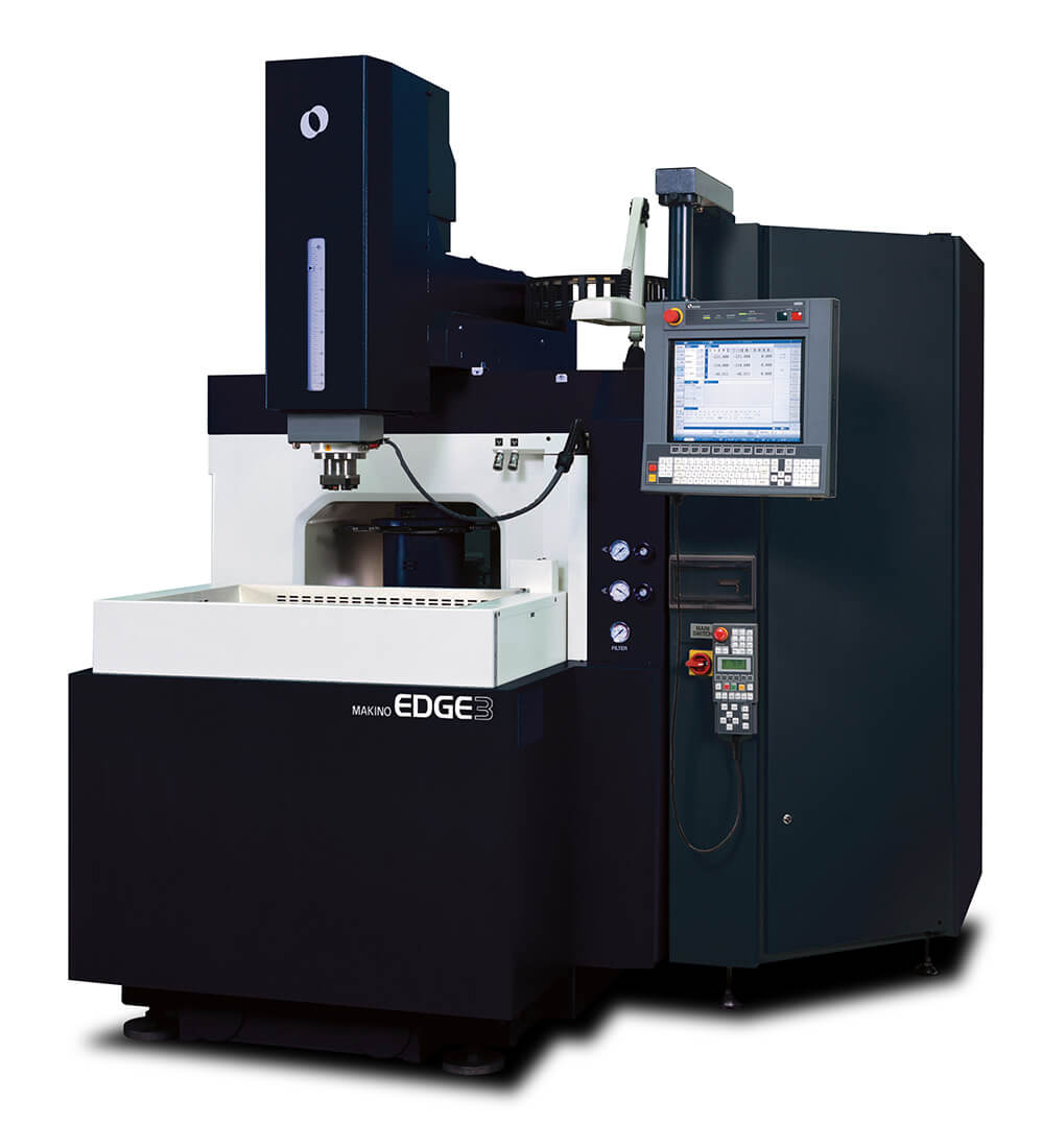
SINKER EDM
2 units
MAKINO
EDGE3i
X / Y / Z axis travel mm
X
450
Y
300
Z
320
Manufacturer image · EDGE3 series
Also listed: CHENGYANG AL435H 2 units
Quantities: April 2026 equipment register. Travel: manufacturer model specifications.
Axis travel is not the maximum machinable part size. Usable space depends on the electrode, fixtures, tank clearance and access; feasibility is reviewed against your drawing.
02 / FROM FEATURE TO PROCESS
The geometry comes first.
The route follows.
A blind form and a through profile need different access. Explore the machining route, then agree how the finished feature will be located, finished and checked.
BLIND & RECESSED FEATURES
Reach the cavity.
Keep the reference.
A shaped electrode reaches cavities and local internal details beyond practical turning or milling access.
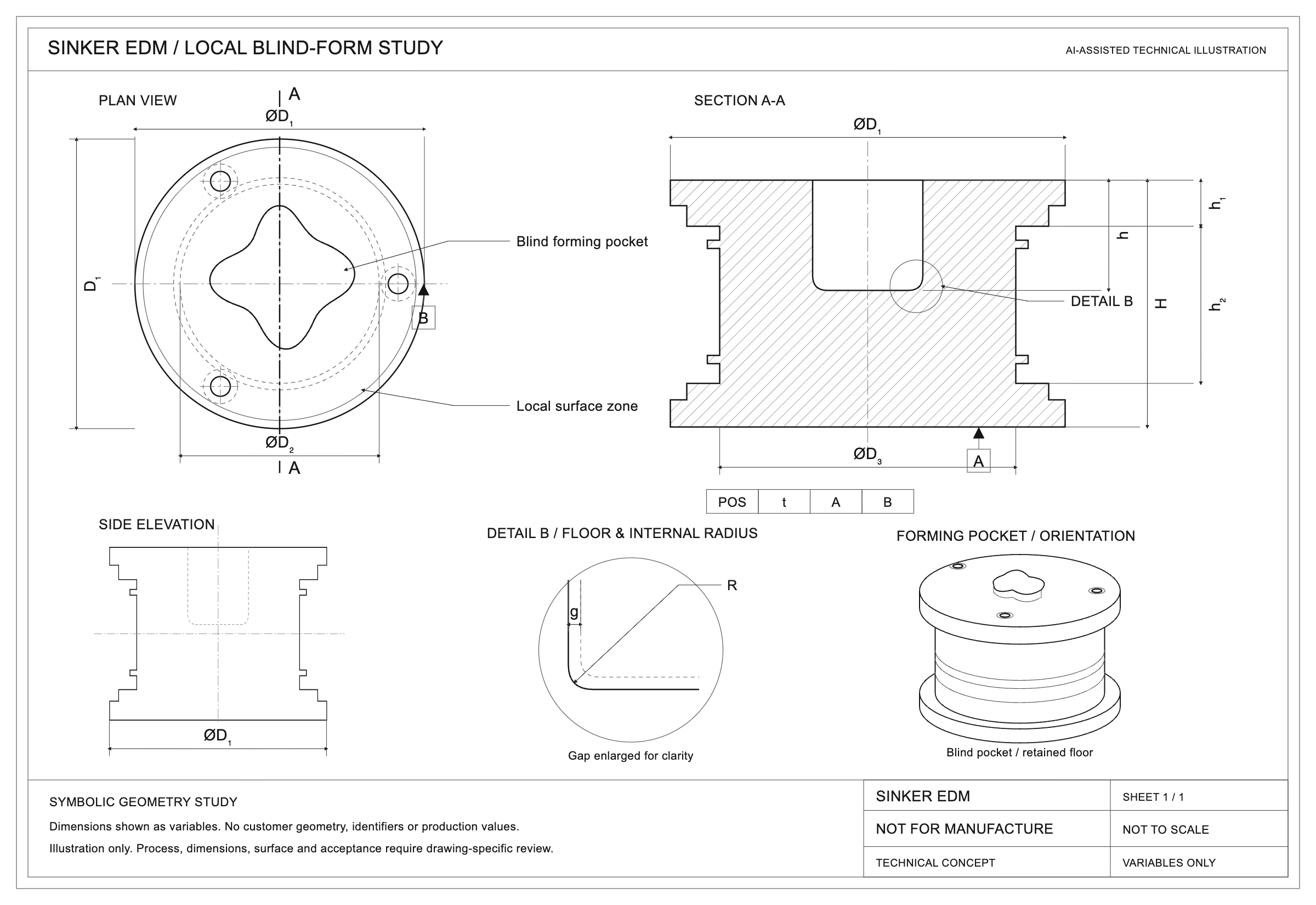
Depth and dielectric access
Show the opening, full depth, changes in section and adjacent protected surfaces. The electrode and holder need a feasible approach. Deep narrow features also need dielectric exchange and debris removal.
Electrode and final surface
Electrode shape, machining gap, wear and finishing allowance are reviewed together. Electrode material, quantity and separate roughing or finishing electrodes depend on the feature. Mark surfaces to be polished and texture to be retained.
Local EDM within a larger route
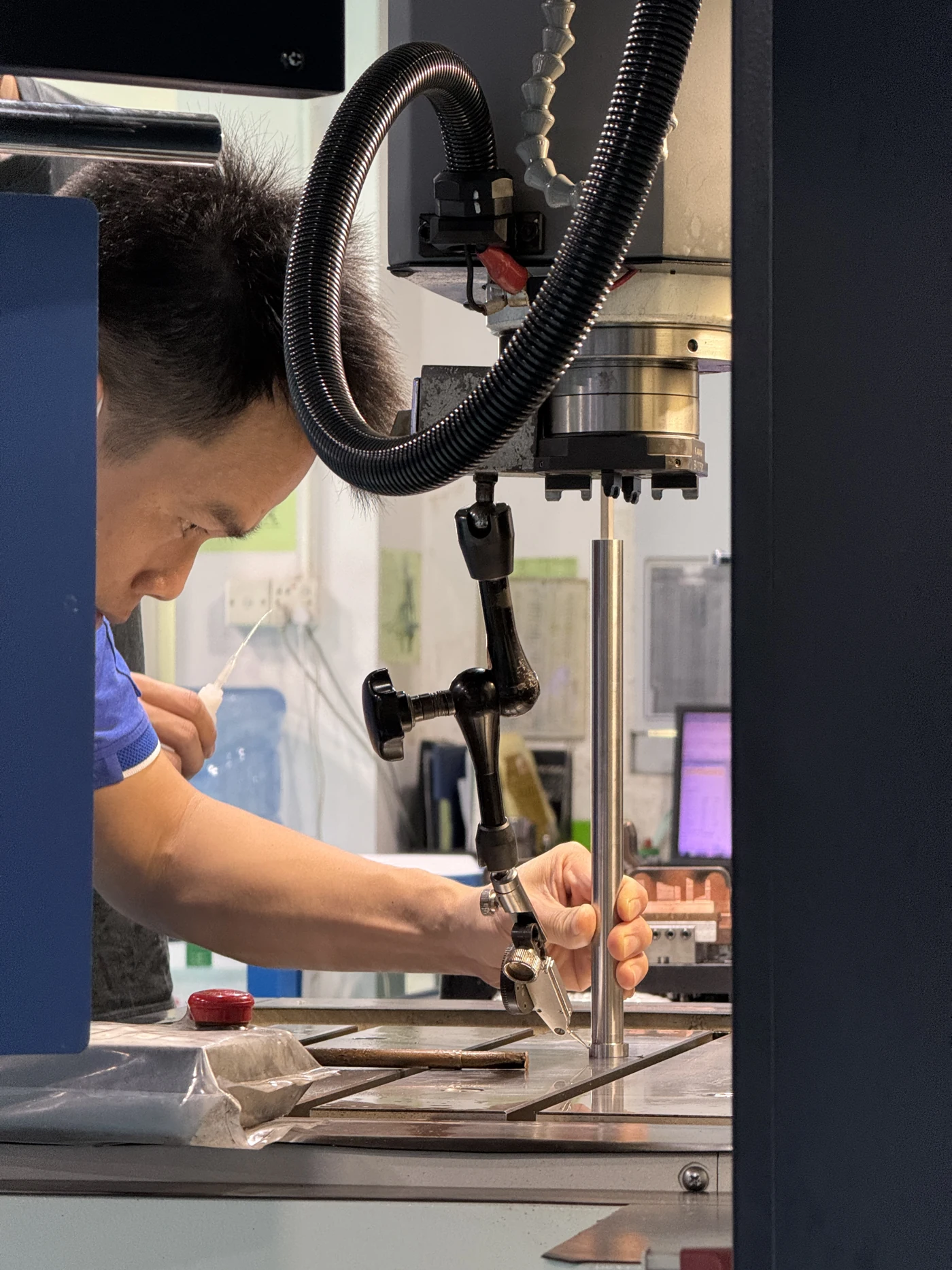
Recorded route fragments include a local internal bore assigned to EDM after turning, and front-end forming on a central core alongside earlier locating operations. These are process-coordination examples; geometry and acceptance remain specific to each part.
FEATURE
Blind forms & local slots
REVIEW
Electrode, gap & access
AGREE
Depth, radius & surface
THROUGH CONTOURS & OPEN PROFILES
A continuous path.
A defined contour.
A travelling wire electrode cuts a continuous through profile, including internal windows and fitting contours.
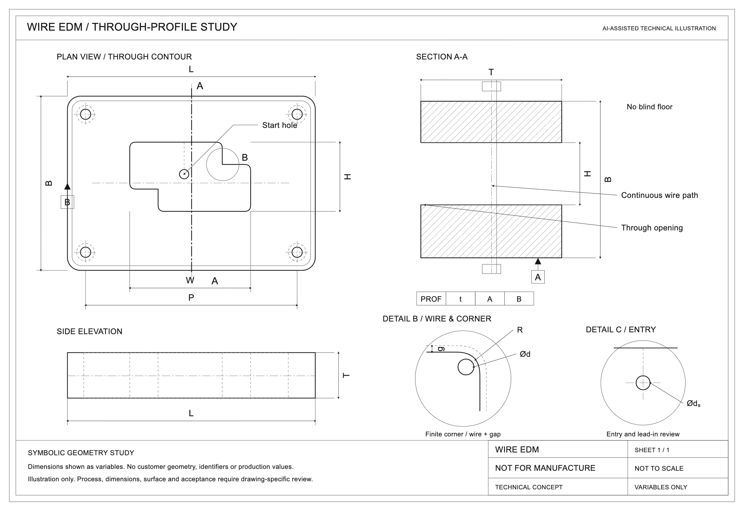
Access and lead-in
For a closed contour, identify a start hole or another route for threading the wire. Show where the cut may join the finished contour and which surfaces cannot carry a lead-in witness mark.
Thickness, taper and support
State cut height, changes in thickness, taper direction and heat-treatment condition. Thin walls, retained stock and cut-out removal affect support and the sequence of subsequent operations.
Corners and finishing cuts
The wire and discharge gap leave a finite internal corner radius. Specify the minimum acceptable radius, contour tolerance and surface requirement. Finishing-pass count and conditions are reviewed for the material and geometry; no fixed count is assumed.

Specifying oil-dielectric wire cutting?
Include the exact material and condition, drawing revision, functional reason for the dielectric requirement and surface acceptance criteria. State whether the dielectric is mandatory or another route may be considered.
Review the proposed machining scope before quotation. Sinker EDM dielectric does not by itself establish oil wire EDM capability.
FEATURE
Windows & through profiles
REVIEW
Wire entry, support & gap
AGREE
Contour, corner & finish
DATUMS, SURFACES & INSPECTION
Keep the reference.
Define the acceptance.
The local shape, its position and the finished surface need separate requirements. Agree the checks while reviewing the route.
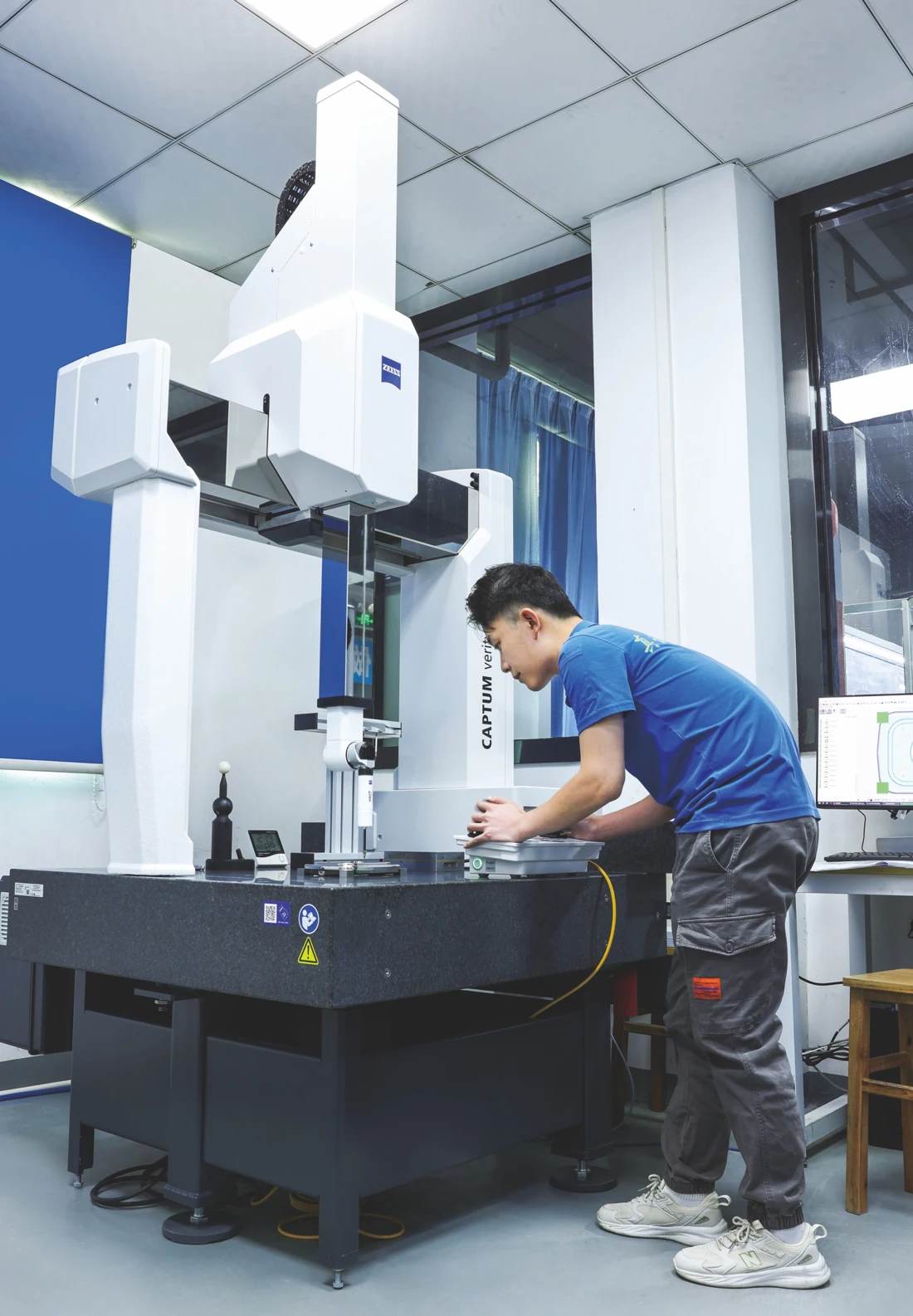
Carry the datum through the route.
Relate turning, milling, EDM and final inspection to the finished-part references, including any locating stock removed later.
Separate final and unfinished surfaces.
Mark retained EDM texture, polishing zones, fitting faces and remaining allowance. Specify the minimum permitted internal radius.
Match the check to the accessible feature.
Agree critical dimensions, contour or form, surface evidence and reporting scope. Probe access and feature visibility affect the method.
Surface texture & integrity requirements
Mark finish zones and the required designation or approved reference. A VDI instruction, visible texture and measured roughness are distinct records; one does not establish the others.
Recorded EDM instructions include VDI 18 for an internal molding surface and VDI 6 for a slider-pin molding surface. These are surface-zone instructions, not measured Ra results or interchangeable finish grades.
Where specified, agree restrictions on the EDM-affected surface, edge condition and fitting allowance. Specialist surface-integrity evaluation is a project requirement, not assumed routine testing for every part.
Equipment context & inspection scope
The April 2026 register lists five SODICK AD32LS units, two MAKINO EDGE3 units and two CHENGYANG AL435H units. Measurement equipment includes a ZEISS CMM and vision measuring equipment. Machine records provide context; feature-specific tolerance and inspection remain drawing-dependent.
Review accessible faces, depths and datums for contact measurement. Visible through contours may suit optical evaluation when the edge, lighting and reference setup can be defined. Deep or hidden details need their own access assessment.
Identify the drawing revision, feature references, limits and reporting format. Surface or fit evidence must be specified separately from dimensional results. A machining-status or shipment record is not an inspection result.
REFERENCE
Finished-part datums
SURFACE
Texture & finishing zones
EVIDENCE
Feature-specific checks
EDM requires an electrically conductive workpiece. Hardness alone does not determine the route.
03 / COMPONENT FEATURES
Start with the detail
that matters.
Locate the molding surface, slot or bore on your drawing. Review it together with the fitting faces and the rest of the component.
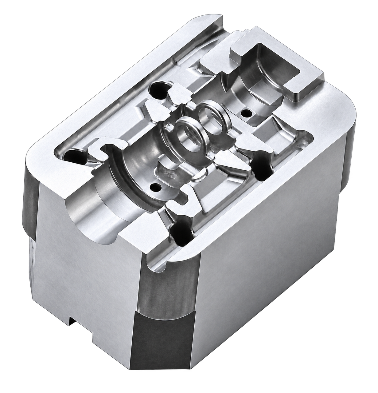
Local forms & insert faces
Identify the cavity, shut-off edge and finished locating references.
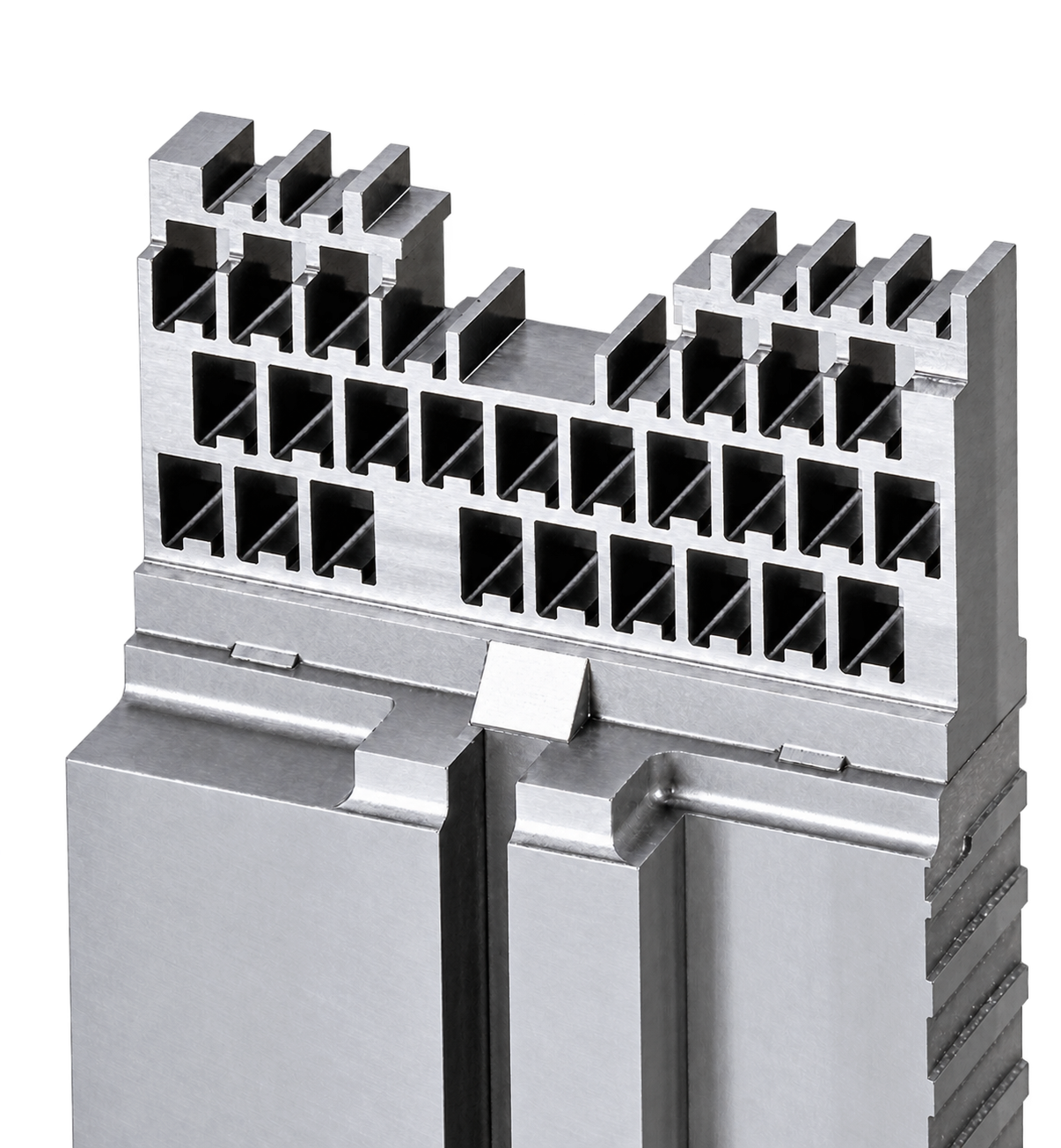
Slots & profile details
Mark the local slots, corner limits and required profile.
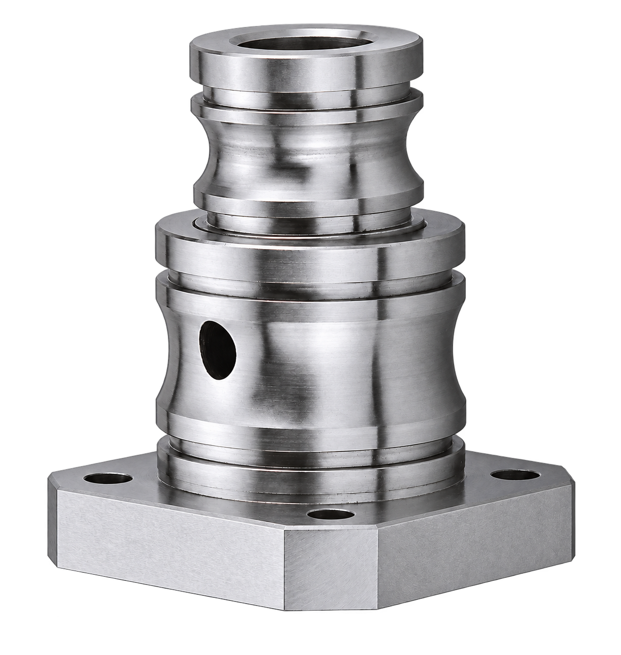
Bores & locating faces
Identify the bore positions, locating faces and mating relationships.
AI-assisted edits of existing product photographs: background removed and clarity enhanced. Original source photos are linked beneath each image. Images do not establish material, machining route, tolerance or acceptance.
Core features & process boundaries
For core front-end and slender features, show how the forming detail relates to the locating diameter, shoulder or reference face. Agree an inspection approach where direct access is difficult.
A local EDM operation does not imply that the whole component, sleeve or bore is made by EDM. Turning, grinding and subsequent finishing remain drawing-specific route decisions. Manufacturing a mating component does not establish assembled movement, service life or performance.
04 / BEFORE YOUR DRAWING REVIEW
Start with your drawing.
Point out the critical feature.
For a new component, replacement part or repeat batch, mark the EDM feature, its function and the references that control fit.
NDA required? Mention it before sharing detailed drawings.
INCLUDE WITH YOUR RFQ
Drawing & geometry
Current drawing revision, available sections or 3D data, blind or through feature, depth, thickness, minimum radii and entry access.
Material & acceptance
Grade and condition, datums, fitting relationships, surface zones and inspection or reporting requirements.
Quantity & supply scope
Batch size, required date and complete-component or selected-operation scope. For replacement or repeat parts, include the applicable revision and mating context.