Products / Precision Plastic Mold Components
Custom · Drawing-based mold components
Precision Plastic Mold Components.
Made for the function.
Custom forming, fitting, sliding and ejection components. Reviewed around the surfaces that matter in your plastic injection mold.
CNC MACHINING · EDM · GRINDING & FINISHING
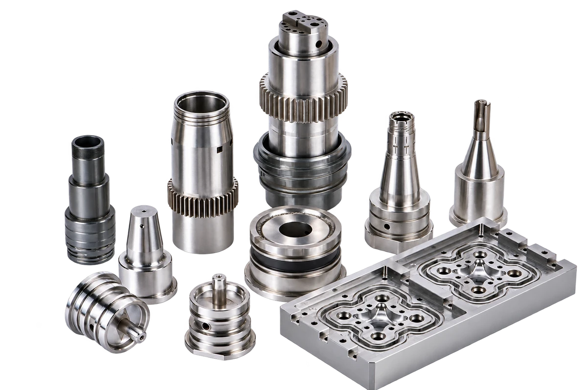
Catalogue photograph with background removed. Geometry and requirements are reviewed for each RFQ.
Component examples / Catalogue photography
A closer look.
Four component studies.
Browse the geometry. Select a photograph to enlarge it, or use the source link below each study.
Four catalogue component studies · Select a photograph to enlarge.
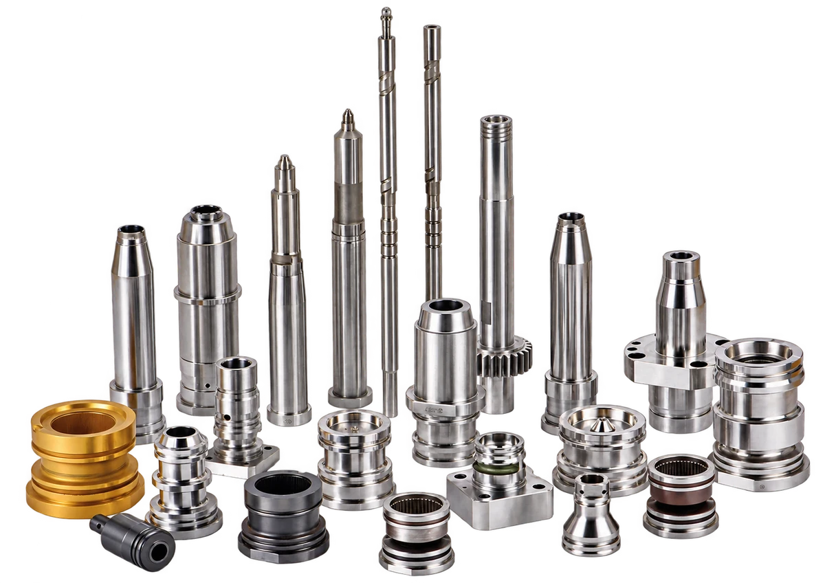
01 / Profiles, bores & support
Round & stepped components
Shoulders, bores and stepped profiles, shown as complete components.
Catalogue photograph · background removed
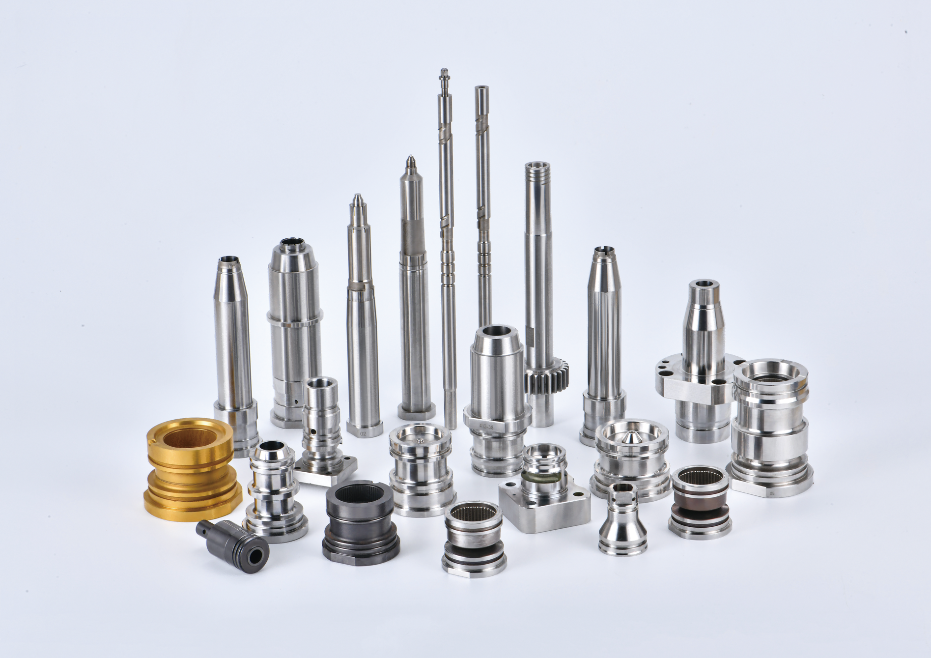
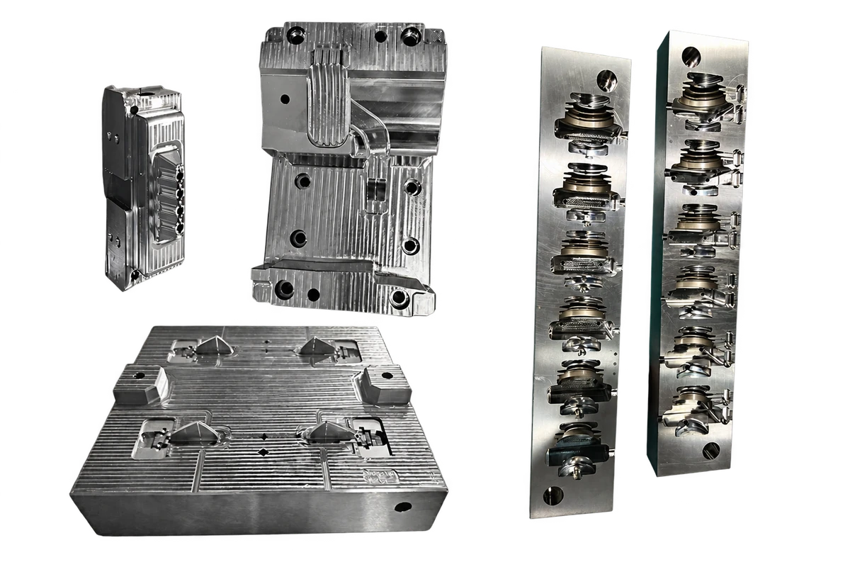
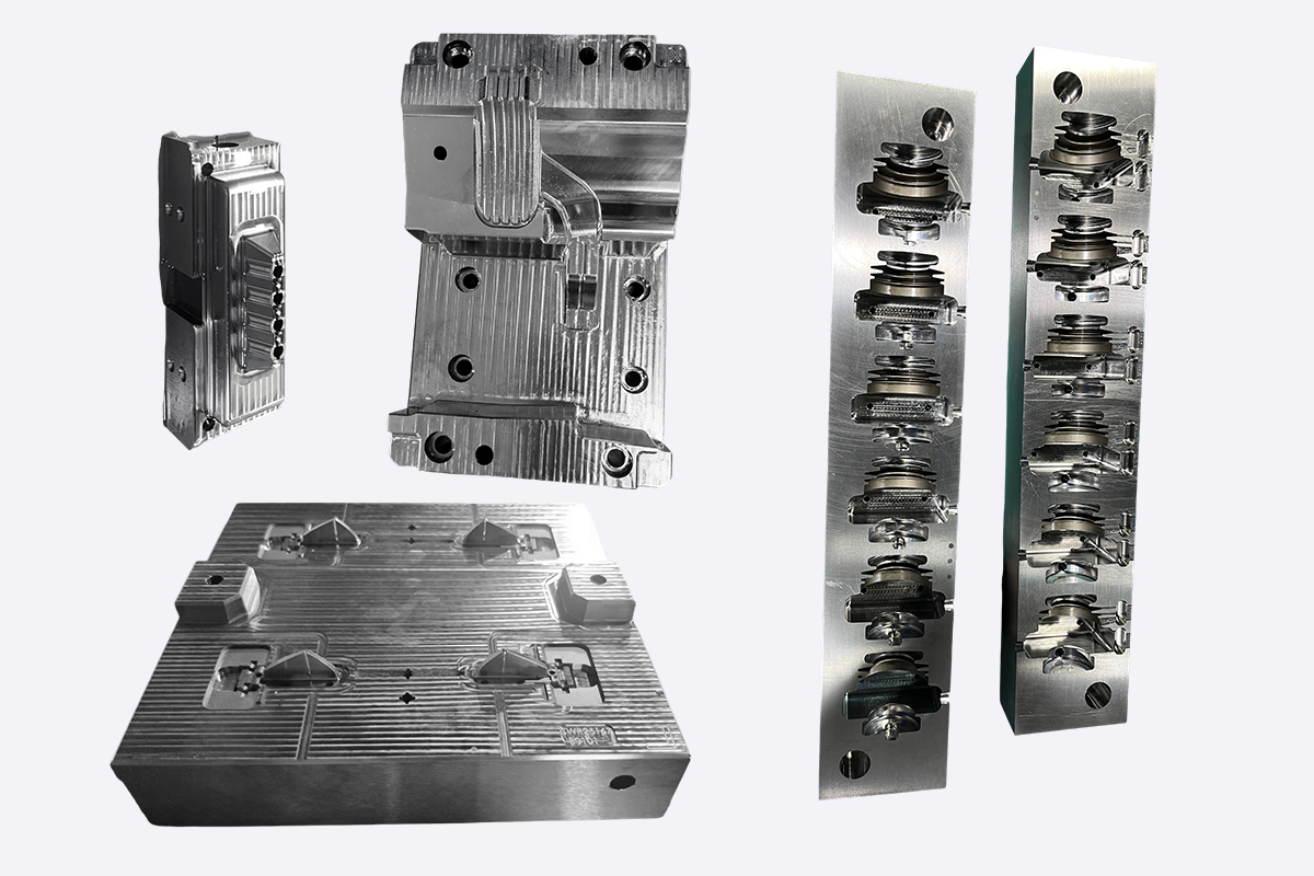
02 / Pockets, contours & interfaces
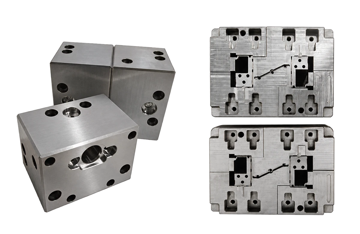
Multi-feature component sets
Several machined faces, pockets and interfaces within a component set.
Catalogue photograph · background removed
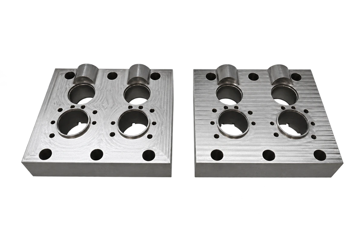
03 / Hole patterns & mating faces
Bored & forming inserts
Through features, counterbores and planar faces with related positions.
Catalogue photograph · background removed
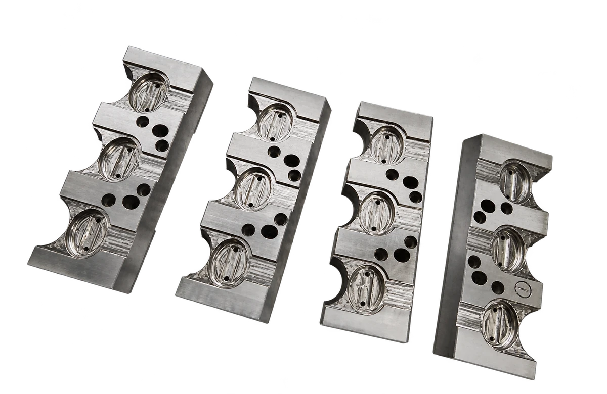
04 / Recessed profiles & local features
Contoured forming details
Repeated recessed profiles and local edges across a set of forming inserts.
Catalogue photograph · background removed
Background removed from original catalogue photographs. Source photographs are linked below each study.
02 / Function & drawing review
Show the function.
We review the features.
A custom part can form plastic, locate another component or guide movement. Mark the surfaces that matter and show what they mate with.
Component study
+
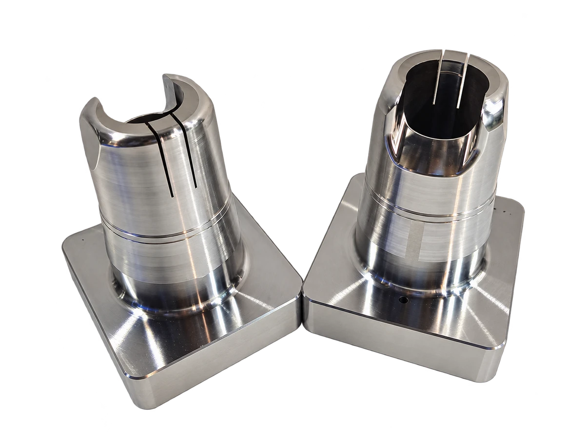
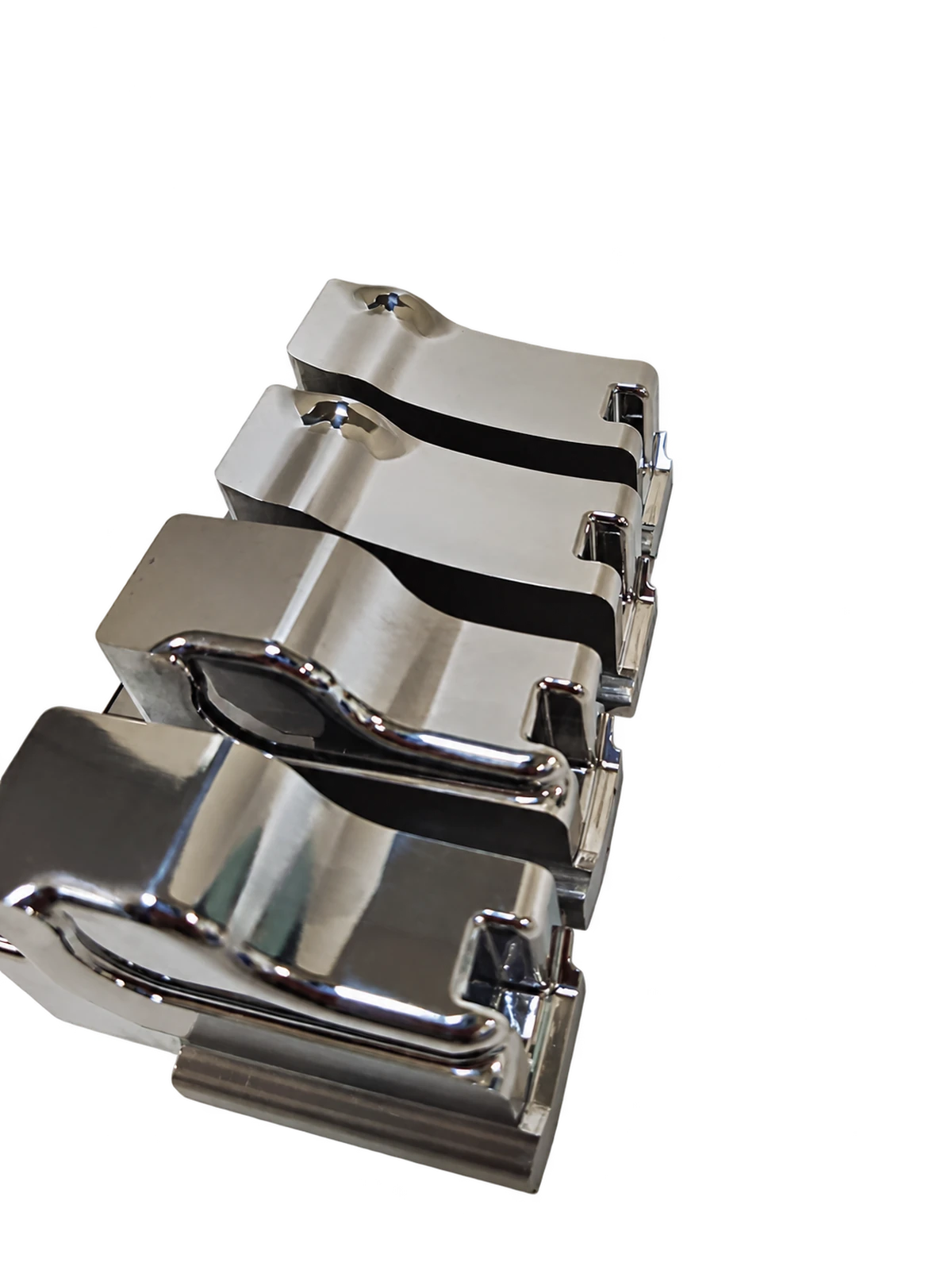
Geometry examples
Geometry. Function. Fit.
01
Form the plastic
Identify molding faces, local radii, shut-off edges and the required surface condition.
Drawing review notes
Mark on the drawing
Molding face, local radii, shut-off edges and protected areas.
Include for review
Surface specification, texture or polish notes and the governing revision.
Actual function and requirements are defined by your drawing.
02
Locate & mate
Show datums, locating bores, fitting faces and the relationship to the mating part.
Drawing review notes
Mark on the drawing
Datum faces, locating bores, steps and fitting surfaces.
Include for review
Mating drawing, assembly section, fit requirement and measurement reference.
Actual function and requirements are defined by your drawing.
03
Guide, eject & support
Mark the motion direction, contact zones, passages and mounting interfaces.
Drawing review notes
Mark on the drawing
Travel direction, guiding faces, stops, contact zones and passages.
Include for review
Relevant assembly view, clearance requirements and the component supply scope.
Actual function and requirements are defined by your drawing.
A useful starting package
Drawing & revision · material · quantity
Critical features · mating / assembly view
Surface zones · requested inspection records
No standard part name needed. Mark what is confirmed and what remains open.
Functional areas & mating information
Custom component scope
SENLAN reviews custom mold components for forming, fitting, sliding, ejection and supporting functions in plastic injection molds. Tell us which surfaces matter, what the part mates with and what needs to change.
Functional area
What needs attention
Useful information for review
Forming
The profile in contact with plastic, local radii, shut-off edges and the specified surface condition.
Highlight the molding face. Identify texture, polish and edges that must remain sharp or have a defined radius.
Fitting & locating
Datum faces, locating bores, steps, contact faces and the relationship to the mating component.
Show the mating drawing, fit requirement and measurement datum. Identify surfaces intended for final fitting.
Sliding & ejection
Travel direction, guiding surfaces, contact zones and clearance around moving features.
Provide the motion direction and relevant assembly view. State which faces guide, stop or push.
Passages & support
Hole connections, passage access, mounting interfaces and supporting faces.
Show passage sections, sealing interfaces and any required continuity checks. Define the component supply scope.
Mark by function, not by appearance. A polished face, a threaded hole or a complex shape alone does not define how the component works. Use your drawing notes to identify the actual requirement.
Drawing checklist & incomplete information
Drawing inputs / Start with what you have
No standard name?
The drawing is the starting point.
Have a special part that does not fit a standard product name? Start with the drawing and the job it needs to do.
No standard part name required. You can begin with a photo or a short description.
Use a drawing number, an internal description or a marked photo to identify the component. A 2D drawing defines dimensions and tolerances; a 3D model helps explain geometry, access and the relationship between features.
When information is incomplete
Send the available version and list what is still open. Separate confirmed dimensions from estimates. Photos can explain wear or assembly position, but they do not establish dimensions, material grade or fit.
If the model and drawing disagree, identify the governing revision before manufacture. Do not leave a critical surface requirement to visual interpretation.
How to mark a functional face
Circle or color the area and add a short note: “molding face,” “locating datum,” “sliding contact” or “leave for fitting.” Include the mating part or assembly section when clearance or contact is important.
RFQ input checklist
Drawing & revision Current 2D drawing, available 3D model and the document that governs any conflict.
Critical features Datums, fit dimensions, geometric relationships, threads, holes and edge requirements.
Material & treatment Exact specified grade, heat treatment, coating and supplied-material conditions, where known.
Surface zones Polished, textured, sliding and fitting areas. Use the stated surface specification rather than a visual comparison.
Project context Quantity, new or replacement part, target timing and any mating parts available for checking.
Documents required Priority dimensions, requested inspection records and any material or treatment documentation.
From a mold feature to a daily task
Small details.
Real-world uses.
Three application examples, viewed through the plastic features your mold needs to form.

Personal care / flip-top closures
A shampoo bottle in the shower.
The hinged cap closes the bottle and exposes the dispensing opening when lifted.
Features to review
Hinge web, sealing plug, dispensing hole and shut-off edges.

Home hygiene / dispensing pumps
Hand-wash at the basin.
Soap dispensers bring actuators, closures and internal pump parts together in everyday use.
Features to review
Stem bores, guide surfaces, collar threads and mating diameters.
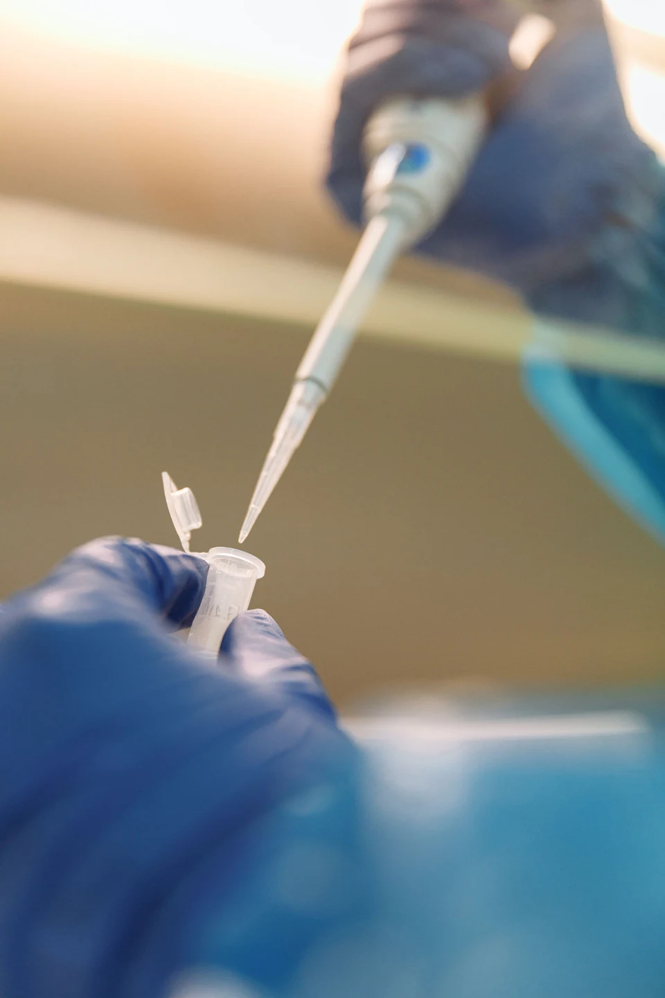
Laboratory / sample preparation
Transferring a laboratory sample.
A disposable tip transfers liquid into a sample tube; both depend on controlled molded geometry.
Features to review
Tip taper, internal profile, thin walls and the tube’s closing features.
Illustrative application scenes. Component selection, actual end use and mold function are reviewed against the part and assembly drawings.
03 / Machining & finishing
One part.
A considered route.
Geometry, access, material condition and critical surfaces determine the sequence. Review small grooves, thin edges and intersecting holes early.
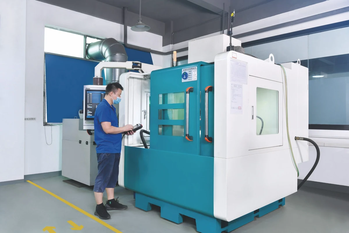
01 / Build the geometry
CNC machining
Accessible planes, bores, steps and contours.

02 / Reach the detail
Sinker EDM
Recessed profiles and conductive features that need electrode access.
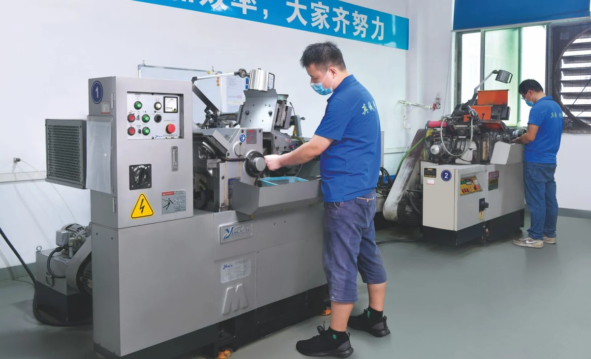
03 / Finish the interface
Grinding & finishing
Datum faces, suitable cylindrical features and final fitting surfaces.
Original workshop photographs. The process route and inspection scope are agreed for each drawing.
Process sequence, finishing & outside operations
01 / Build the geometry
CNC machining
Accessible planes, bores, steps and contours.
02 / Reach the detail
Sinker EDM
Conductive features and recessed contours that need electrode access.
03 / Finish the interface
Precision grinding
Datum faces, thickness, steps and suitable cylindrical features.
Heat treatment and outside processes
Heat treatment and other external operations are coordinated within an agreed scope. Material identity, treatment requirements and the checks needed after return should be specified. Deep-hole drilling and coating requirements are reviewed individually.
What is agreed before manufacture
The drawing revision, material, critical features, finishing areas, external-process responsibility and inspection deliverables. A project route is selected for the part; an equipment specification alone does not guarantee its tolerance.
Local features, allowances & protected edges
From the overall part to local features
Review the small features that change the route
Narrow grooves, local steps, thin edges and intersecting holes may need different tools, access or inspection methods. Identify these features early, together with the datum that controls their location.
For a fitting edge, state whether it is to be finished to drawing or left with an agreed allowance. For a molding face, specify the required finish and the edges that must not be rounded during polishing.
The photograph illustrates visible features only. It does not identify material, tolerance, surface grade or the customer’s mold application.
Measure the feature in its reference
Check the datum.
Then the dimension.
Agree the critical characteristics, measurement reference and records you need. The method must suit the feature, access and specified tolerance.
Select a feature group to explore the method. Photographs show equipment in use, not a measured result for the displayed components.
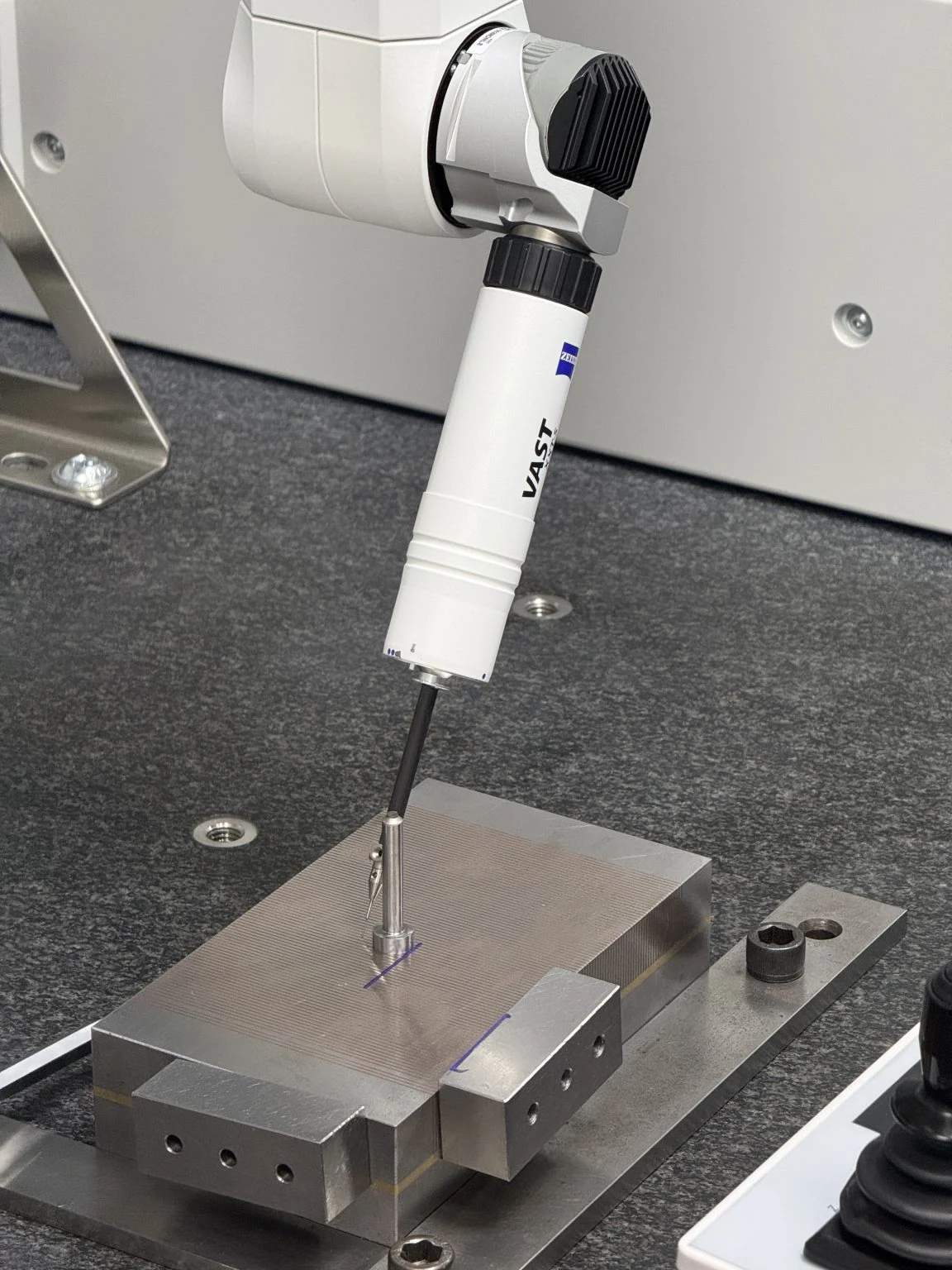
Datum relationships
Accessible 3D positions and geometric relationships.
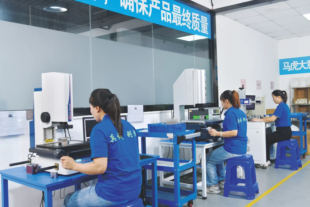
Visible profiles
Contours, holes and clearly defined edges.
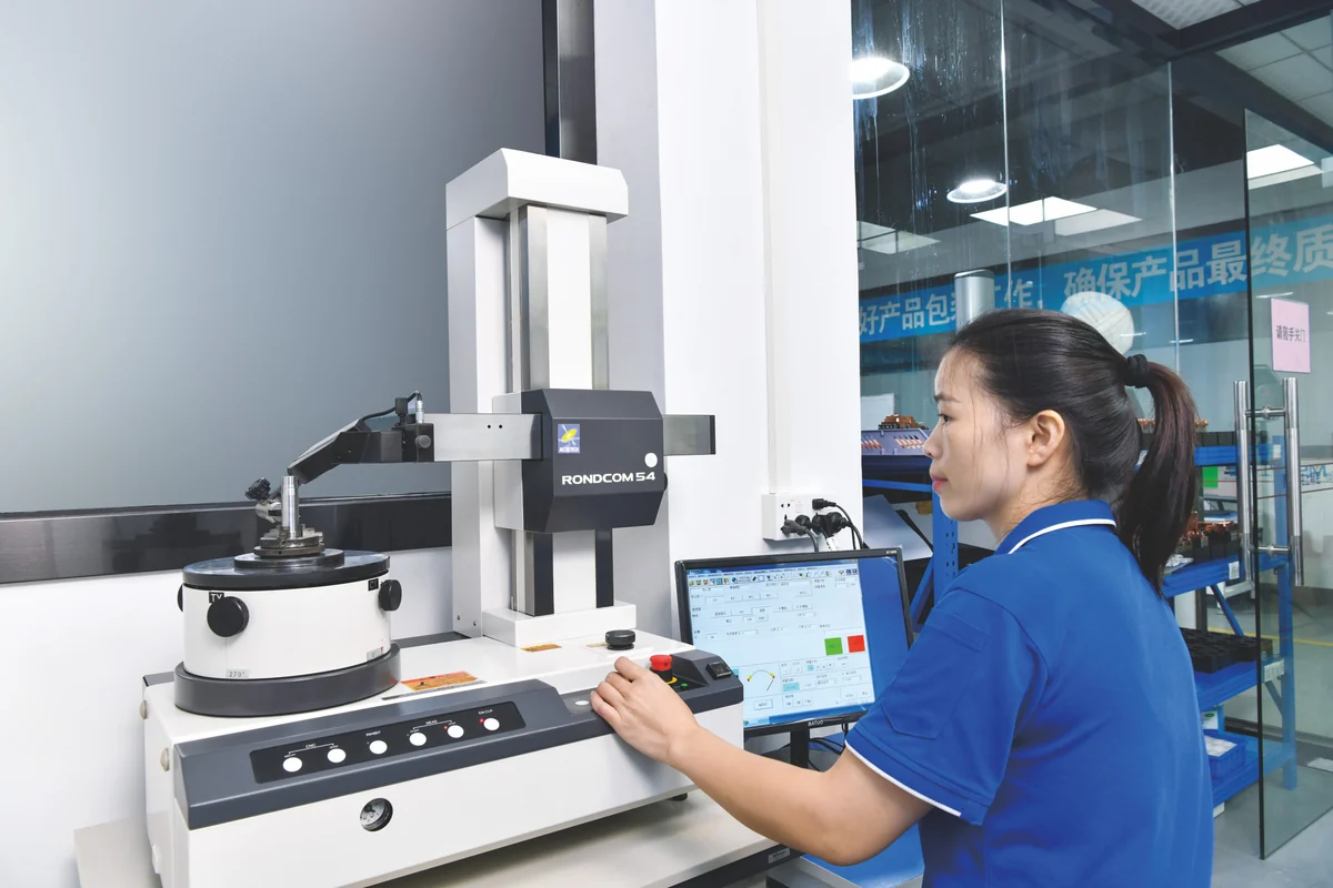
Rotational features
Cylindrical geometry, where specified and applicable.
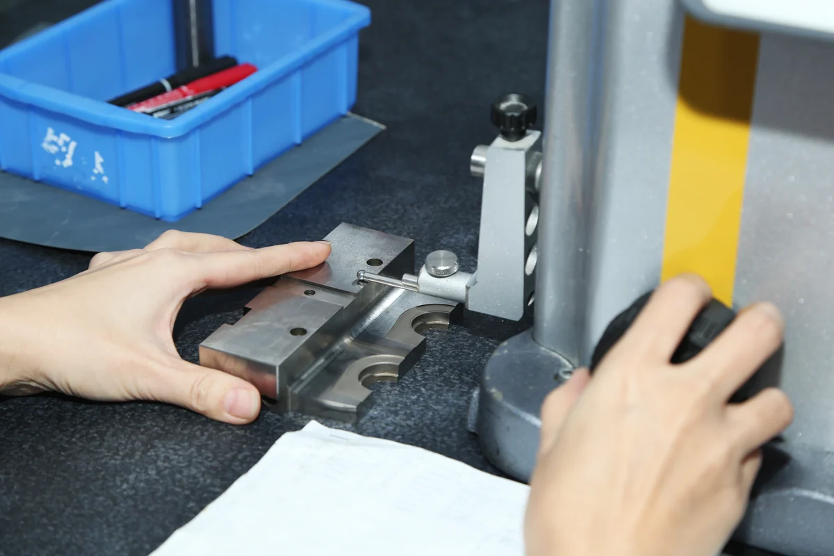
Sizes & steps
Height and reference checks suited to the feature.
Original library photographs. Component inspection is separate from mold fitting, mold trials and customer acceptance.
Inspection methods & requested records
Measure what controls the function
Inspection follows the feature and its datum
Agree which characteristics need recorded results and how they relate to the drawing. Size checks, profile checks and geometric relationships are different tasks; the method needs to suit the feature, its access and the required tolerance.
Dimensions and datum relationships CMM checks can address accessible three-dimensional relationships. Height gauges and micrometers can support suitable size, step and reference checks.
Profiles, holes and local contours Vision measurement or profile comparison may suit visible two-dimensional features. The drawing reference and edge definition need to be clear.
Surface and treatment requirements Specify the finish or treatment document needed. Appearance alone does not establish roughness, hardness or coating performance.
Documents within the agreed order scope Request recorded critical-dimension results, material documents and treatment records as applicable. Availability and the required detail are confirmed during review.
Dimensional inspection of a component is separate from fitting in the mold, mold trials and customer acceptance.
Recorded custom orders & evidence scope
H13 blade ejector component
A two-piece order was recorded as completed and shipped. Hardness and DLC were specified as order requirements. Final dimension and coating results are separate records.
H13 cavity insert
A one-piece order was recorded as completed and shipped. The record supports this order scope and status. It does not establish the final forming profile, measured surface condition or mold trial result.
Coordinated AL6061 base plate supply
A two-piece base plate order was recorded as completed and shipped, with external manufacture identified. This is a supporting supply example and does not represent all machining performed in-house.
Use the record for what it actually shows
Order requirements, completion and shipment each describe a specific part of the project. Material documents, measured results, fitting checks and customer feedback need to match the same part and revision before they can describe a completed technical case.
Related product families
Find your component.
Background-removed catalogue examples. Actual function is defined by your drawing.
Precision Mold Inserts
Forming faces & local details
Core & Forming Components
Profiles, shoulders & bores
Complex Mold Components
Geometry & mating interfaces
Sleeve Components
Bores & outer profiles
04 / Your drawing. Your requirements.
A clear start.
A part made to your drawing.
New part, replacement or modification: define what stays, what changes and what the component must do.
New componentCurrent drawing + functional faces
ReplacementMating dimensions + wear information
ModificationMarked changes + fixed interfaces
Start with what you have
Send the drawing.
Tell us what matters.
- Current revision and available 3D model
- Material, quantity and target timing
- Critical features, datums and mating parts
- Surface zones and inspection documents
You can enquire without a file. Use the existing RFQ’s confidentiality option if an NDA is needed first.
Typical project sequence
Confirm the drawing revision, material, mating information and requested records.
Review the route, datum transfers, finishing areas and any coordinated outside operations.
Agree the recorded checks, document scope, packing and dispatch arrangements for the order.
Lead time and progress updates are agreed for your component.
New, replacement & modification scope
New custom component
Send the latest drawing and available assembly context. Identify the surfaces that form plastic, locate the part or contact a moving component.
Replacement from a drawing or sample
Provide the governing drawing, wear photos and mating dimensions. A worn sample cannot by itself define the original nominal dimensions or clearance. Confirm these before manufacture.
Mold modification
Mark the changed features and interfaces that must remain. State whether the supplied model represents the original or revised part. Separate component manufacture from fitting and trial work.
Lead time & progress reporting
Lead time by component
Planned around your part.
Size, geometry, critical features and quantity shape the route. Material availability, heat treatment, finishing and inspection also affect the schedule.
01Drawing review
02Machining & finishing
03Inspection & dispatch
The quoted lead time, start condition and planned dispatch date are confirmed for each order.
Progress updates
↗
Your order, clearly reported.
Agree a production progress table and reporting frequency with your contact. Use the component revision to keep updates tied to the work being reviewed.
Part number / revision
Identify the work
Current operation
See where it stands
Next step
Know what follows
Target dispatch
Review the schedule
Suggested report fields · agree with your contact
Before you send an RFQ
Can I request a quote without knowing the part name?
Yes. Use your drawing number or a short description and attach the available drawing, photo or assembly view. Explain what the part does and which surfaces are critical. A standard catalog name is not needed to begin.
What if the drawing is incomplete?
Send the available information and identify the missing dimensions, material or fit details. Mark estimates clearly. Critical requirements must be clarified before manufacture, so a preliminary discussion should not be treated as a final manufacturing specification.
How should I explain a critical functional surface?
Mark the area on the drawing and state its role, datum, mating component and required condition. For example, distinguish a molding face from a sliding face or a surface left for final fitting. Include an assembly section where the contact relationship is difficult to show.