
01 / SELECTED WORK
Details you can see.
Components we make.
Explore finished mold inserts from our product catalogue. Open a photograph to inspect the geometry, machined surfaces and feature layout.
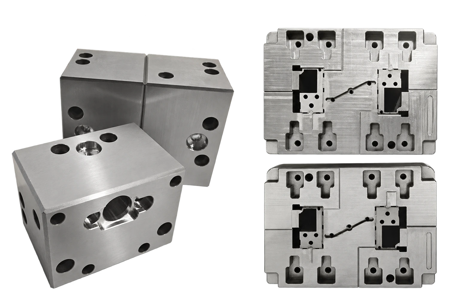
01 / POCKETS & CHANNELS
Multi-feature mold blocks
Pockets, drilled features and locating surfaces brought together in one component.
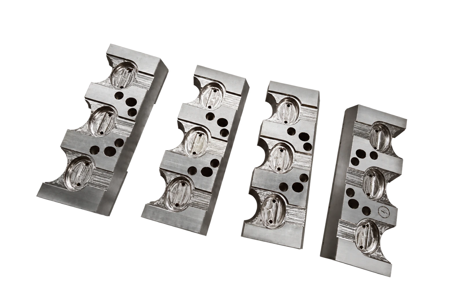
02 / REPEATED FORMING DETAILS
Contoured forming inserts
Repeated contours and recessed features across a series of machined inserts.
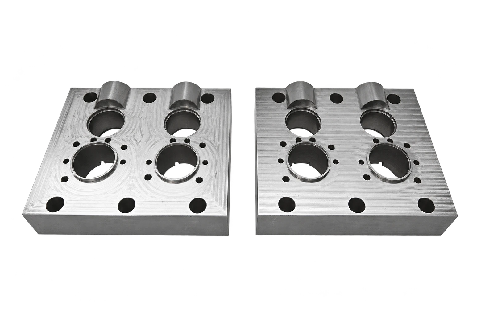
03 / BORES & DATUM FACES
Precision bored inserts
Hole patterns, counterbores and flat faces with defined feature relationships.

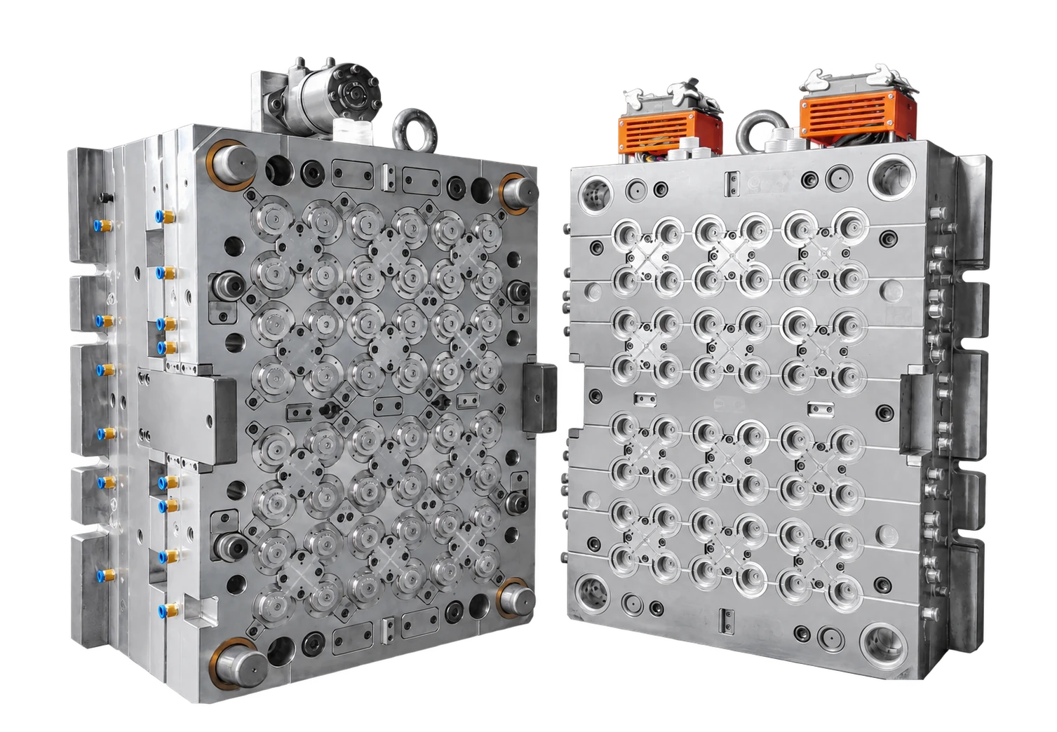
04 / CAVITIES & INTERFACES
Cavity & forming sets
Multi-surface components with recessed geometry and adjacent mating faces.
Made to drawing. Reviewed by feature. Have a similar component? ↗
02 / ROLE IN THE MOLD
The right component.
In the right place.
Choose by the feature your mold needs to form or release. The component geometry is reviewed together with its mating parts and assembly references.
01 / Mold sliders
Side-action assembly
Located beside the cavity to form lateral features and release side undercuts. Review travel direction, guide faces, shut-off surfaces and mating references.
02 / Lifter inserts
Angled release on the core side
Forming tips and inserts at the end of an angled release arrangement. Review the tip geometry, angle, thickness and guide surfaces against the required release path.
03 / Shut-off & fitting inserts
Between opposing mold components
Flat or angled contact surfaces establish the required shut-off and fit around a forming area. Define contact requirements, datums and the final surface condition.
04 / Collapsible core components
Within a segmented core assembly
Segments and mating components support the release of internal undercuts. Feasibility depends on the segment interfaces, assembly clearances and related mold geometry.
From mold features to everyday products.
Typical application areas · reviewed for each component

PACKAGING & CLOSURES
Caps & closure features
Side details, snap features and fitting interfaces in molded closures.

BEAUTY & PERSONAL CARE
Caps & pump components
Forming details, guide surfaces and release features for packaging parts.
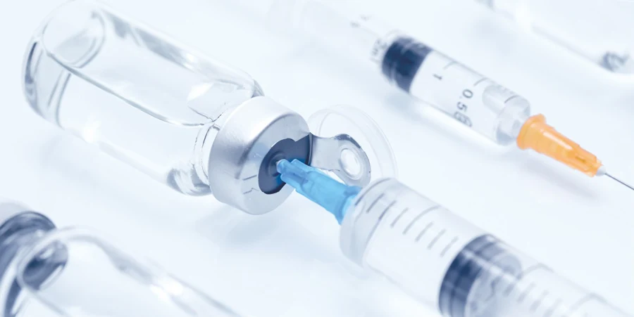
MEDICAL & LABORATORY
Medical plastic components
Ports, clips and internal features assessed against the mold design.
Packaging and beauty images are AI-expanded application illustrations. Medical imagery is from the company catalogue. These illustrate industry contexts, not completed customer projects.
03 / MACHINING & INSPECTION
Made by the feature.
Checked for the fit.
CNC milling, sinker EDM and grinding play different roles. The process route and inspection plan follow the drawing’s functional surfaces.
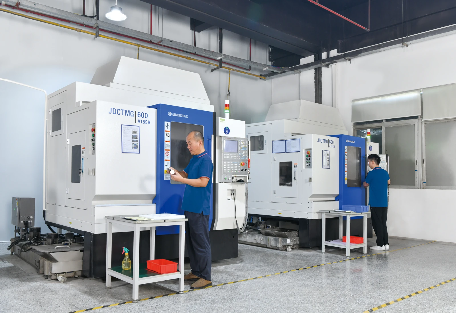
01 / BUILD THE GEOMETRY
CNC milling
Accessible contours, pockets, holes and angled faces.
Equipment & accuracy record
JINGDIAO CNC
Recorded actual accuracy: 0.005 mm.
Confirm the tolerance for your feature, size and material.
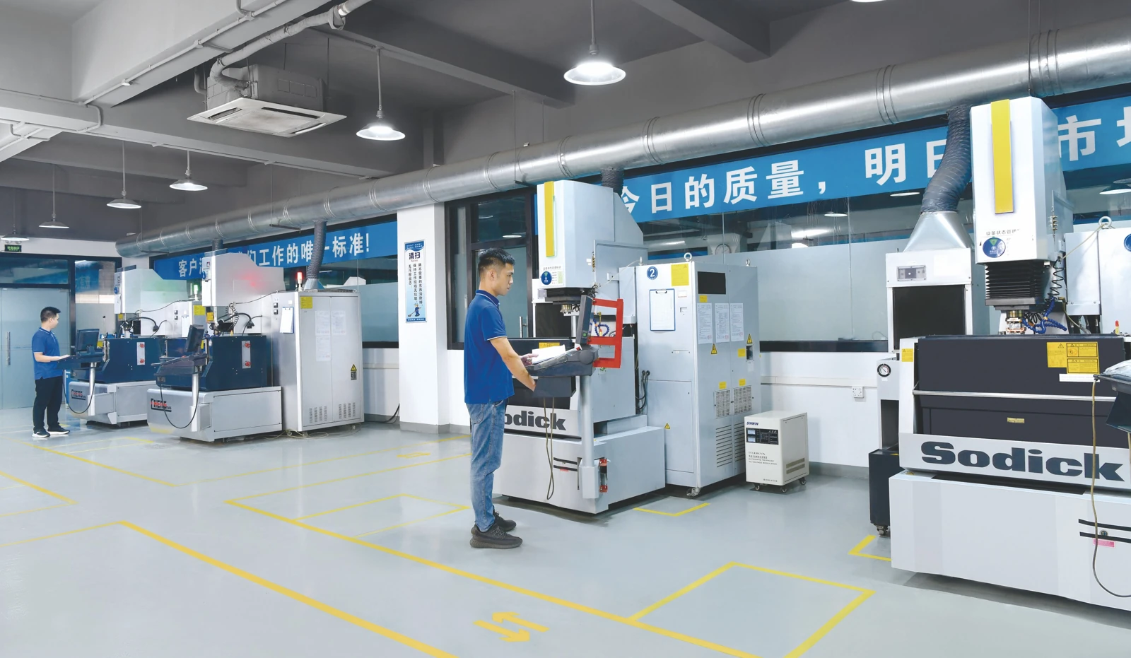
02 / REACH THE DETAIL
Sinker EDM
Recessed contours and electrode-defined forming details.
Equipment & accuracy record
MAKINO EDGE3: 0.005 mm
SODICK EDM: 0.01 mm
Recorded actual accuracy; electrode access and final requirements are reviewed.
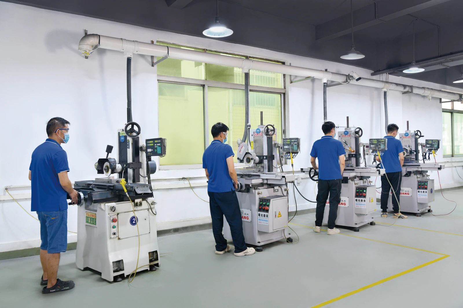
03 / FINISH THE INTERFACE
Precision grinding
Accessible flat faces, steps, datums and thickness dimensions.
Equipment & accuracy record
SHUGUANG surface grinding
Recorded actual accuracy: 0.002–0.003 mm.
Final condition and accessible geometry are reviewed.
Equipment records describe operation-level capability, not a universal finished-part tolerance. Drawing requirements, final material condition and inspection methods are agreed for the order.
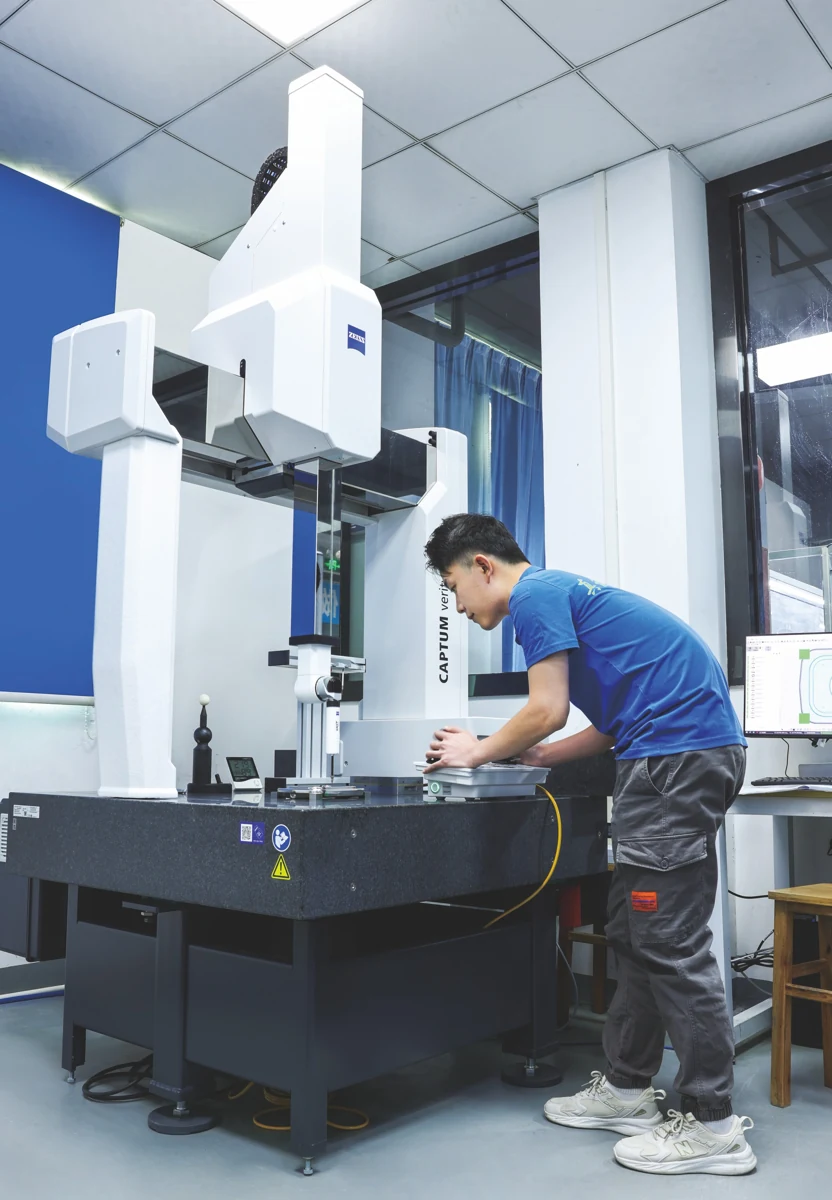
MEASURE WHAT CONTROLS THE FIT
Geometry, datums
and functional dimensions.
Inspection is selected for the feature, access and specified tolerance. Agree the critical dimensions and required records before production.
ZEISS CMM
Dimensional relationships
Vision measurement
Accessible profiles & details
Height measurement
Steps, faces & references
04 / FROM REVIEW TO DELIVERY
A clear route.
A contact who keeps you informed.
Your delivery schedule is based on the component. Your project contact shares a production progress table at the agreed reporting frequency.
LEAD TIME BY PRODUCT
Planned around your part.
Size, complexity, critical tolerances and quantity shape the route. Material availability, heat treatment, finishing and inspection affect the schedule.
01Drawing review
02Machining & finishing
03Inspection & dispatch
The quoted lead time, start condition and planned dispatch date are confirmed for each order.
REGULAR PROGRESS UPDATES
Your order, clearly reported.
Receive updates from your project contact in a progress table. Agree the frequency and report fields at the start of your order.
Part number / revisionIdentify the work
Current operationSee where it stands
Next stepKnow what follows
Target dispatchReview the schedule
Suggested report fields · Confirm with your contact
LET’S REVIEW YOUR COMPONENT
Show us the geometry.
Tell us what must fit.
Send your drawing, model and mating references. We’ll review the component scope, machining route, inspection and delivery requirements.
YOUR DRAWING REVIEW STARTS WITH
01 / 2D drawing & 3D model
02 / Material & final condition
03 / Quantity & target date
04 / Critical features & mating parts
Continue to our RFQ form to share your files and project requirements.
BEFORE YOU SEND
Can you quote from a sample?
Share photographs and the available drawing first. Worn samples may not represent the intended dimensions; original or mating parts may be needed for review.
What tolerance can you achieve?
We review each feature against geometry, size, material, final condition and inspection access. Equipment accuracy records are a starting point, not a blanket part tolerance.
How is the delivery date confirmed?
The date follows a review of your component, quantity, material and processing route. The quotation sets out the agreed lead time and start condition.
How will I see production progress?
Your project contact sends a regular production progress table at the agreed frequency. Review the current operation, next step and schedule changes with them.