
Custom precision mold components
Core & Forming
Components.
Core pins. Thread cores. Neck rings.
Made to your drawings for new tooling, matched sets and replacement projects. Reviewed around the forming surfaces, mating fits and locating datums.
TURNING · GRINDING · EDM · INSPECTION
Library photograph · background removed and enhanced.
Component geometry and requirements are confirmed from the drawing.
01 / Component types
Core pins, thread cores
& neck rings.
Choose the component by its job in the mold. Images show geometry examples; your drawing defines the functional surfaces and supply scope.
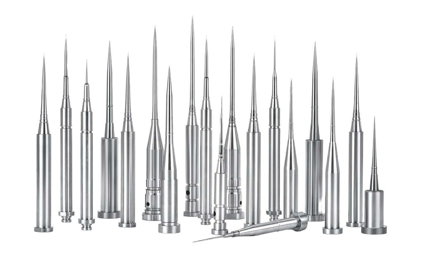
Straight · stepped · tapered · slender
Core pins
Form holes and internal details. Show working length, diameter transitions, forming-end geometry and how the pin is supported.
Library photograph · background removed / enhanced
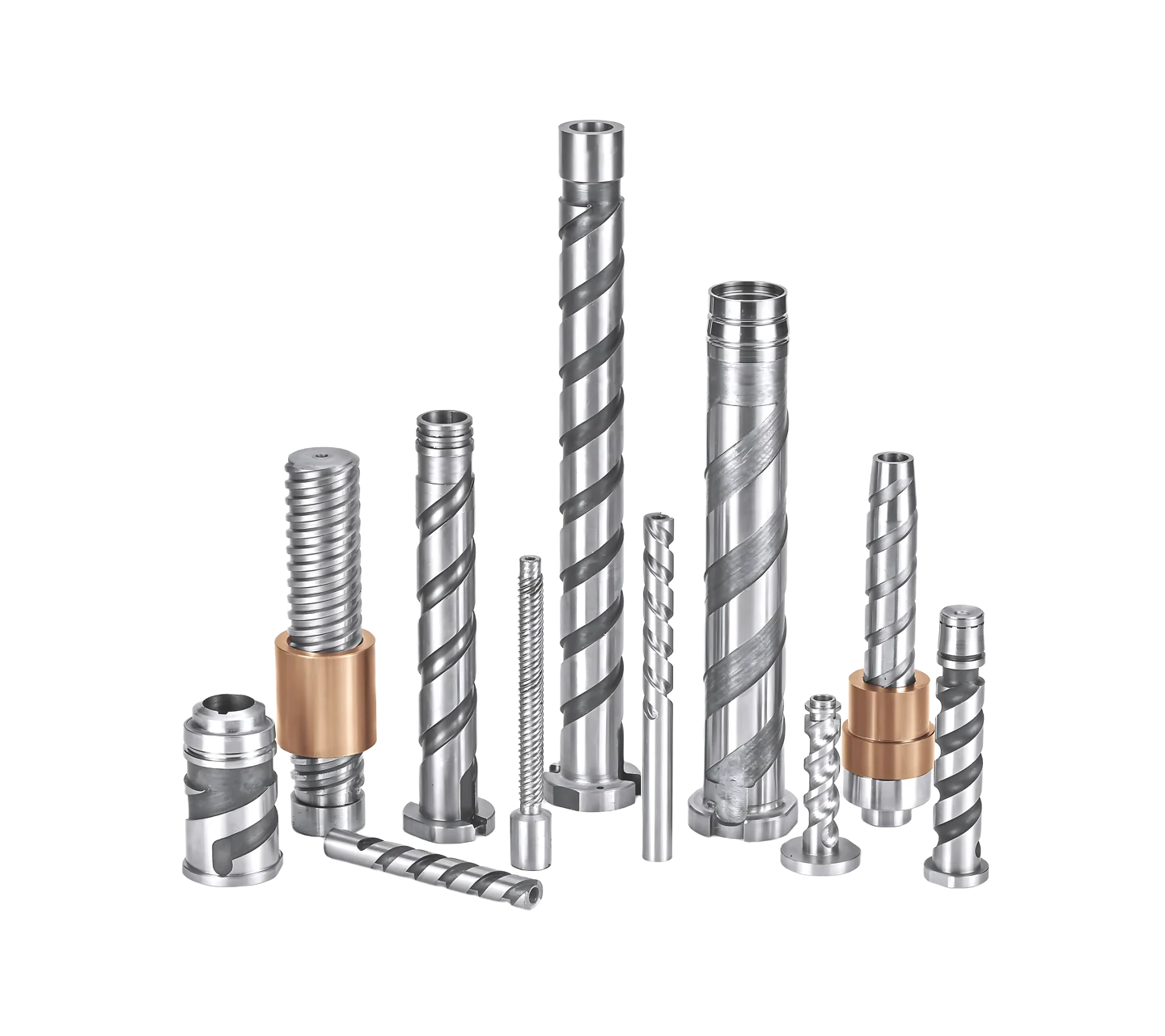
Thread cores · thread inserts
Thread components
Define profile, pitch, lead, handedness and mating references. Identify the forming thread and the geometry that controls release.
Library photograph · background removed / enhanced
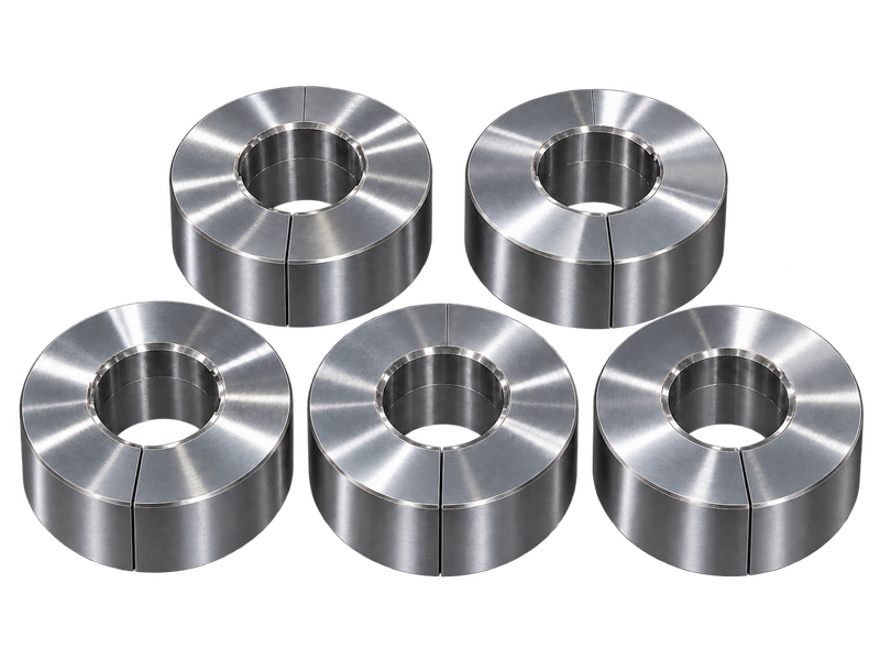
Neck profile · locating faces · split interfaces
Neck ring components
Show the neck or closure profile and any split interface. Identify matched sets, locating faces and the required relationship to mating parts.
Product display · photo-based enhancement
Component scope & geometry — detailed notes
Straight · Stepped · Tapered · Slender
Core Pins
Core pins form holes, internal details and small molded features. Review the working length, diameter transitions, forming end and support conditions. Straightness and coaxial relationships matter alongside individual diameter tolerances.
Thread cores · Thread inserts
Thread Components
Thread cores and thread inserts create internal or external thread-forming features. Define the thread profile, pitch, lead, mating geometry and release conditions. Finishing requirements should identify the forming surface and its relationship to the locating features.
Ring geometry · Split interfaces
Neck Ring Components
Neck ring components help form neck and closure geometry in packaging molds. Review the forming profile, split interfaces where applicable, locating faces and mating fits. Matching requirements across a set should be defined in the assembly information.
02 / Functional surfaces & drawing review
Forming geometry.
Fit & locating datums.
A diameter alone does not describe the component. Connect forming geometry, fitting dimensions and locating references before the machining route is agreed.
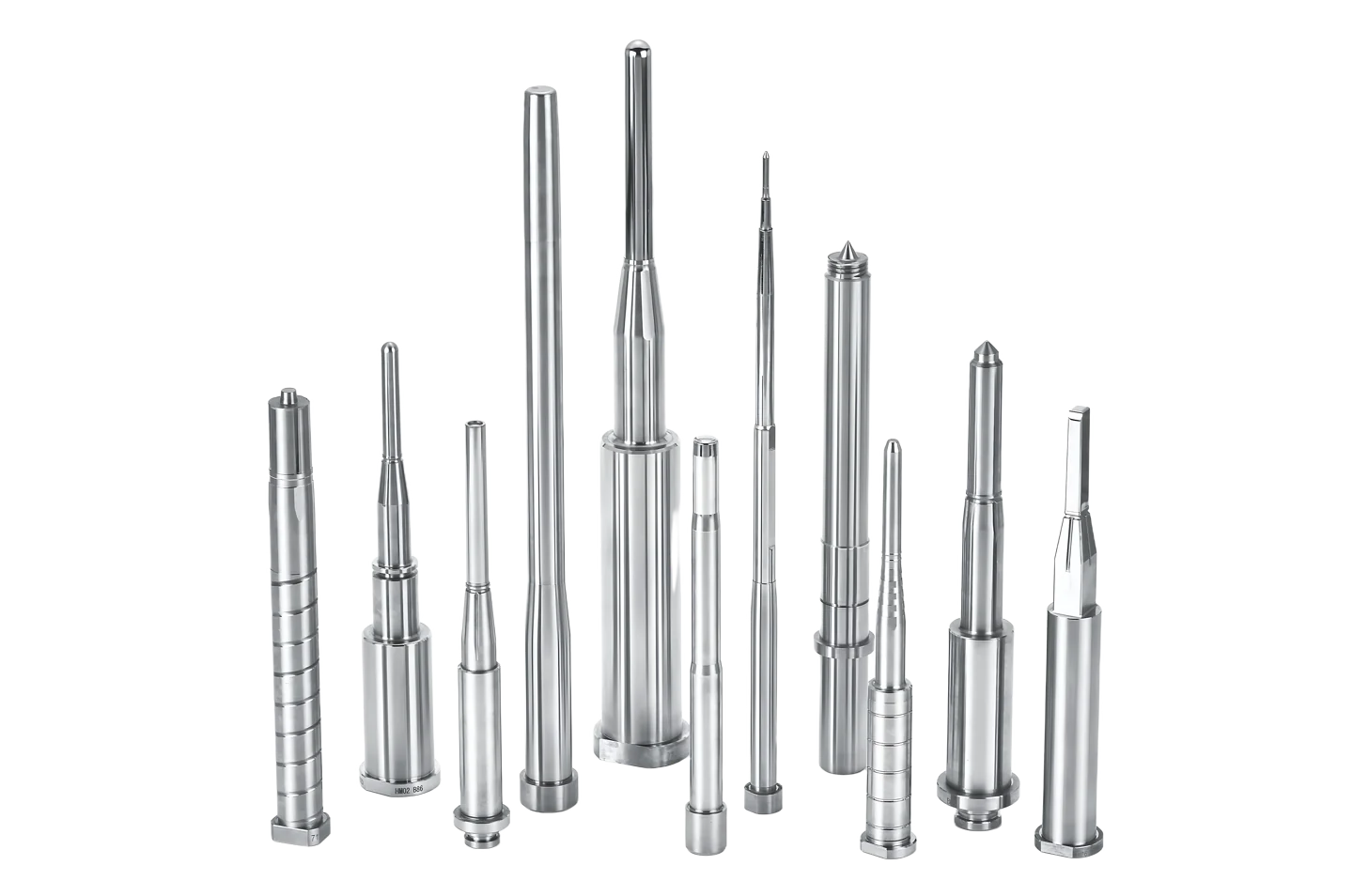
Stepped profiles & locating shoulders
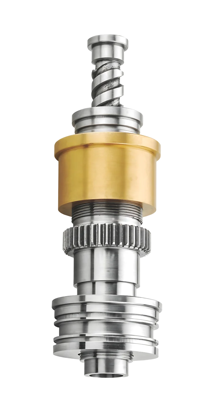
Thread & mating geometry
01
Form the plastic
Mark the molding surface, forming end, thread detail, polishing and texture zones.
02
Fit the mating part
Identify fitting diameters, split interfaces, engagement lengths and matched-set requirements.
03
Locate & support
Show datums, shoulders, end faces and the support conditions for slender sections.
Dimensions, tolerances & functional surfaces
Critical dimensional tolerance ±0.005 mm may be achievable on suitable features, subject to drawing and process review.
Concentricity 0.005 mm may be achievable for suitable geometry and measurable datum relationships.
Diameter and working length Provide nominal values and tolerances for each functional segment.
Straightness and slenderness Identify supported length and measurement conditions. L/D is a review input, not a published limit.
Thread requirements Specify profile, pitch, lead, handedness and the agreed checking method.
Matched components Identify the set, mating references and any interchangeability requirement.
Material and hardness State grade, treatment condition and required hardness.
Surface finish Identify each surface and its Ra, polishing or texture requirement.
Inspection records Define critical characteristics, report scope and part identification with the RFQ.
Conceptual geometry only. Actual functions and datums follow the project drawing.
Forming surfaces Identify molded geometry, thread detail and any specified polishing or texture requirements.
Fitting surfaces Mark working fits, split interfaces and diameter relationships that affect assembly.
Locating surfaces Define datums, shoulders and end faces so the manufacturing and inspection references agree.
Replacement, slender, matched & cooling features
The replacement must fit the existing mold.
Send the current drawing revision and mating dimensions. Identify worn regions separately from the nominal dimensions you want restored. Include treatment or coating allowances at the fit.
A set needs consistent forming geometry.
State whether components must match within a cavity set and how each part will be identified. Define set-level requirements in the quotation and inspection scope.
A slender section is sensitive to support.
Show working length, diameter transitions and mold support. Grinding setup, indicating and support need to suit the geometry; handling between operations also matters.
A cooling feature affects the forming wall.
Show bore locations relative to the outside geometry, minimum wall requirements and inspection access. Passage feasibility is reviewed for the drawing; no universal deep-hole limit is assumed.
A thread or split interface needs an agreed check.
Supply mating references and identify release or assembly features. Clarify whether acceptance is dimensional, functional or both. Keep forming, fitting and locating regions distinct.
An urgent request needs a usable technical brief.
Give the required date, quantity and available references. Separate confirmed requirements from open questions so a quotation can be based on a clear scope.
03 / Typical product applications
From mold components
to plastic products.
Explore three typical uses: laboratory liquid handling, beverage closures and lotion dispensing. Each connects a molded feature to the core, thread or neck-ring geometry that needs review.

Laboratory liquid handling
Pipette tips for sample preparation
Disposable tips transfer small liquid volumes during sample preparation. The mold core defines the internal taper and outlet; tip geometry, core support and forming-surface condition need to be reviewed together.
Related mold components
Slender core pins
Drawing review
Internal taper · outlet geometry · support & finish

Beverage packaging
Threaded caps on bottling lines
Plastic screw caps close beverage bottles after filling. Thread cores form the cap’s internal thread; neck-ring components apply where bottle-neck tooling is included. Confirm which side of the closure interface is in scope.
Related mold components
Thread cores · neck rings where specified
Drawing review
Thread profile · sealing geometry · mating neck

Personal-care dispensing
Lotion pumps in daily use
Pressing the actuator dispenses lotion through the pump. Stepped cores form internal bores and shoulders, while thread components form screw interfaces. Review bore geometry, assembly fits and the relevant sealing surfaces.
Related mold components
Stepped core pins · thread components
Drawing review
Internal bores · shoulder positions · assembly fit
More application context, including connector molds
Medical & Laboratory Molds
Slender core pins for laboratory consumable tooling call for clear forming-end geometry, support conditions and consistency requirements across multiple parts.
Packaging & Closure Molds
Thread components and neck rings connect thread profiles, closure geometry and mating interfaces. Supply assembly references and any matching requirements.
Electronics & Connector Molds
Small core pins and stepped forming details require attention to fine geometry, locating references and fits within closely spaced mold features.
04 / Made & checked
A route built around
the critical feature.
Turning, grinding and EDM can work together. Feature access, support, material condition and finishing allowances determine the sequence.
Reference machining capacity
Machining ranges.
Start with the component size. We review the working range together with the geometry, fixture and tool access.
CNC milling
Length × width, up to
×
mm
Machining height, up to
mm
Sinker EDM
Length × width, up to
×
mm
Machining height, up to
mm
Subject to drawing and process review. Reference ranges are not a guaranteed finished-part size. Usable capacity depends on geometry, workholding, tool access and the required machining route.
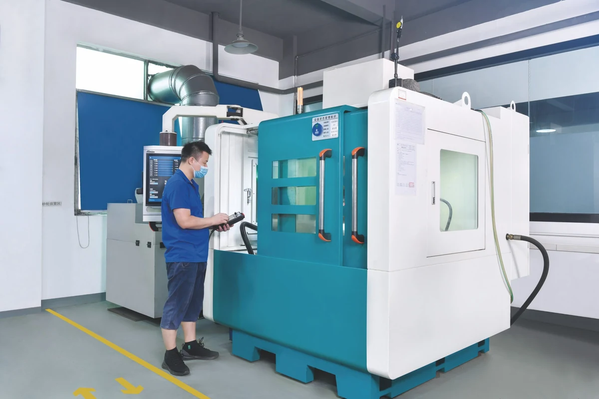
01 / Establish geometry
CNC turning & milling
Round bodies, shoulders, grooves and local features. Review supports, datums and the allowances needed for finishing.
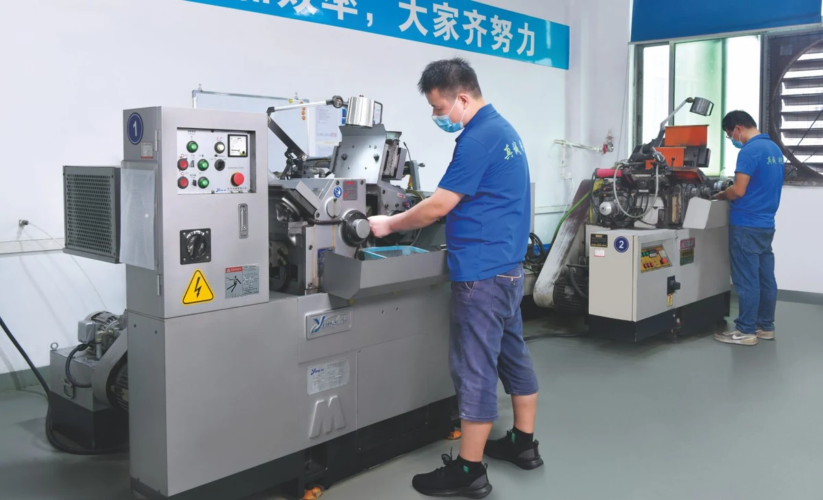
02 / Refine the fit
Precision grinding
Review final diameters and shoulder relationships, with attention to setup, heat and slender-section support.

03 / Reach local details
EDM & detail finishing
Review restricted features, electrode or wire access, surface requirements and the edges that need protection.
Material, treatment
& surface zones.
Specify the grade, hardness and treatment condition. Separate polishing and texture from fitting surfaces; confirm finishing allowances and supplier-supported processes in the project scope.
Setup, first-part checks & process requirements
01 / Establish the geometry
CNC Milling & Turning
Hardinge CNC turning establishes round bodies, shoulders, grooves, end faces and suitable thread geometry. Milling addresses accessible contours, slots and local features. Review the first part before batch production and recheck dimensions during machining for tool-wear effects. The route follows the drawing and finishing allowances.
02 / Refine functional surfaces
Precision Grinding
Review incoming stock allowance, indicating, supports and fixtures before grinding. Temperature and clamping can affect slender features. Establish final diameters, shoulders and datum relationships, then check specified dimensions before transfer to the next operation.
03 / Reach complex details
EDM & Detail Finishing
For restricted cutting access, review EDM or wire EDM around the local feature. Confirm electrodes, reference corners, coordinates and machining locations. Check the first part before continuing a batch. Surface requirements and sharp-edge protection belong in the operation plan.
Inspection / Match the method to the feature
Dimensions, profiles
& datum relationships.
Agree the critical characteristics and required records before manufacturing. Select inspection around geometry, datum references and access.
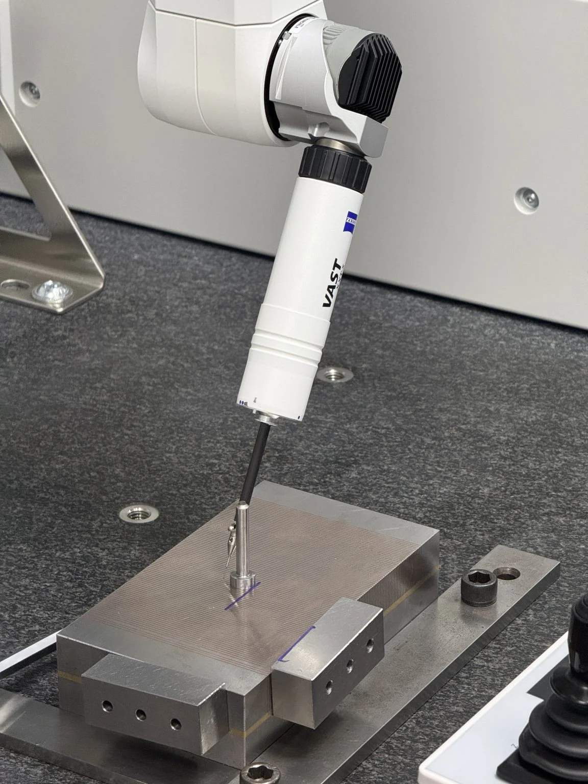
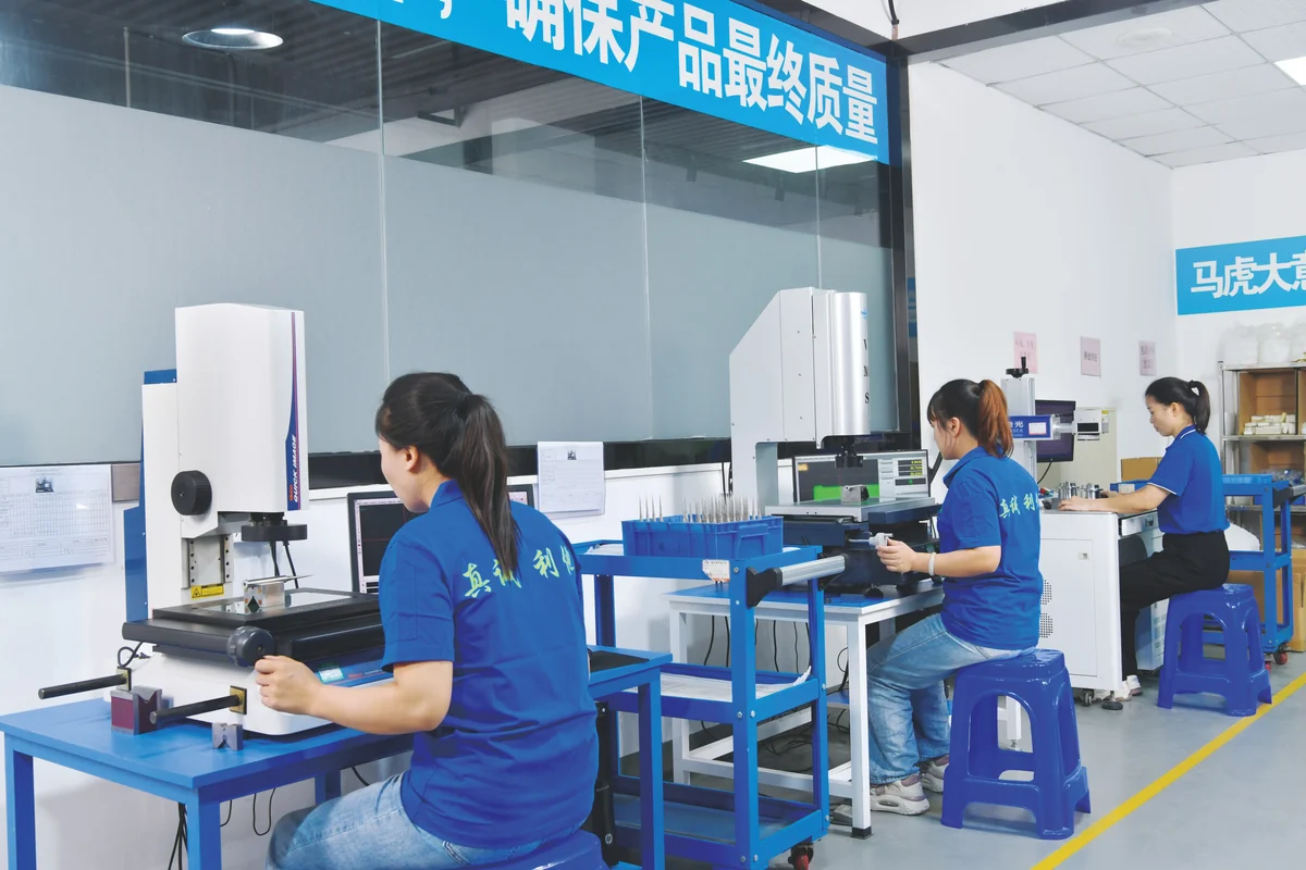
CMM & datum relationships
Accessible position, form and mating relationships.
Profile & thread review
Feature contours, thread details and agreed checks.
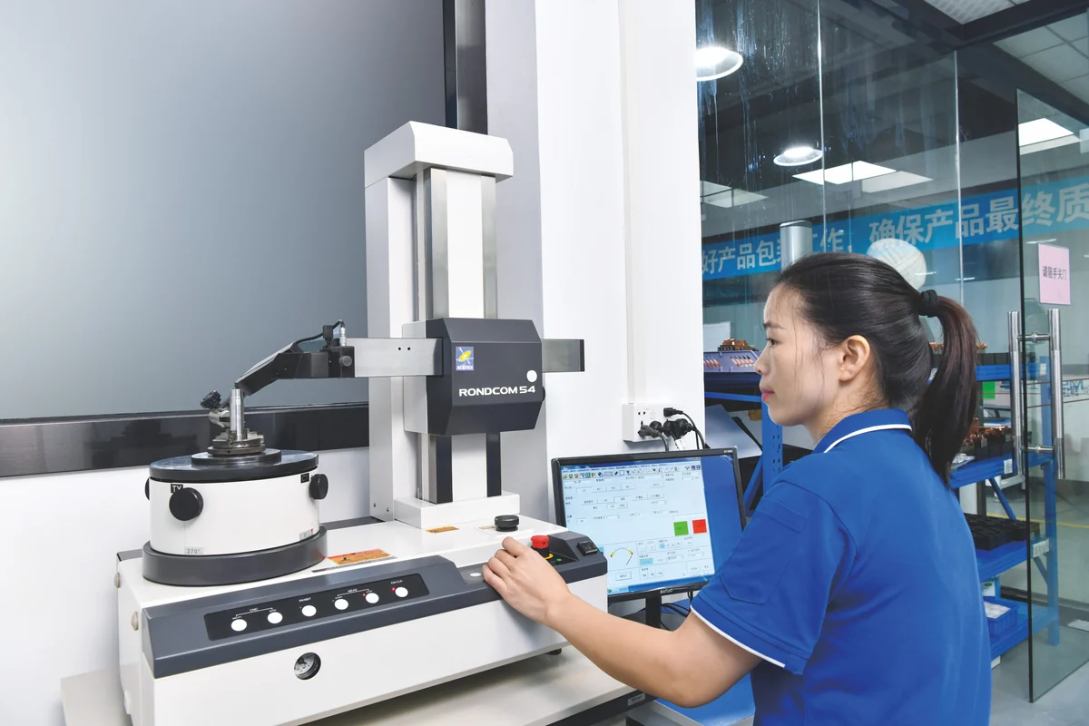
Rotational geometry
Roundness or coaxial relationships where specified.
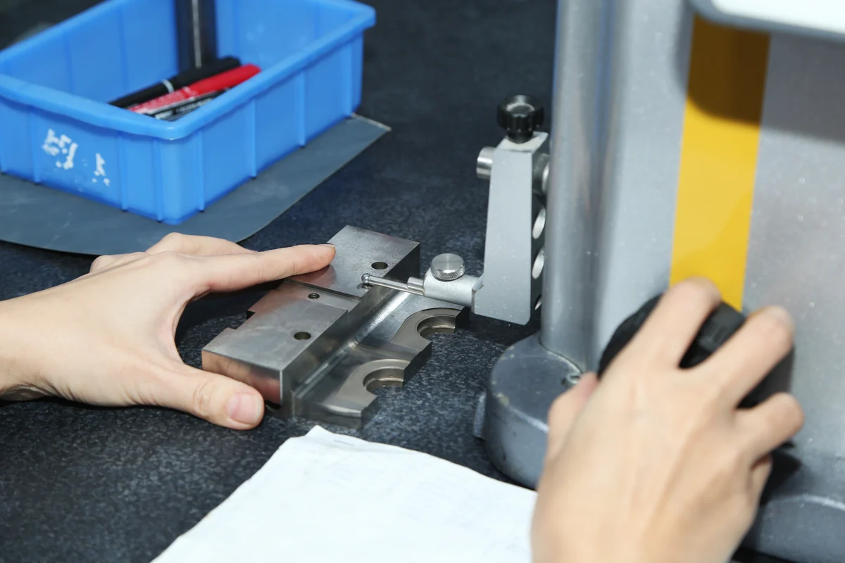
Shoulders & references
Length, step height and end-face relationships.
Drawing-dependent capability
±0.005 mm on suitable dimensional features; 0.005 mm concentricity for suitable, measurable datum relationships. Confirmed after drawing, geometry, material, finishing and measurement review. These are not blanket limits for every component.
Inspection planning & the dimensional record example
Measurement methods must match the feature, access and datum scheme.
A dimensional record with a defined scope
Nominal 38.36 mm · Allowed 38.35–38.37 mm A saved inspection record for a separate mold-component batch contains eight readings from 38.350 to 38.356 mm, a range of 0.006 mm. Those readings fall within that feature’s recorded limits.
This is an example of a specified feature in one batch, not a core-pin capability limit or proof of whole-mold interchangeability. For your order, agree the feature, tolerance, quantity, measuring method and report scope.
Inspection tied to function
Check the relationships that control the fit.
ZEISS CMM inspection is part of the manufacturing team’s measurement resources. Agree critical characteristics and required records before manufacturing. Documented inspection procedures include first-part review, process rechecks and final checks. Select measuring tools for the feature and datum scheme; every feature does not require the same method.
Slender pins: straightness and diameter chain Review suitable diameter, length and straightness checks with the defined support and reference conditions.
Round parts: coaxiality and end-face relationships Select methods around the accessible geometry and datum scheme. CMM is an option where suitable.
Threads: profile, lead and mating requirements Review optical, contact or functional checks according to feature size and the drawing requirements.
Neck rings: split fit and forming profile Review matched interfaces, locating faces and consistency across the required set.
Published reference specifications — project-specific
Representative product image
Pipette-tip core pins
MOLDVANCE reference specification: SUS420 stainless steel, vacuum heat treatment and HRC 48–52. The source describes critical dimensional control to ±0.005 mm where required. These conditions apply to this reference project.
Compare forming diameter, slender geometry, fitting reference and consistency requirements. Send your own specification even when an application looks similar.
Representative inspection image
Replacement core pins
MOLDVANCE reference specification: drawing-reviewed critical features, with ±0.005 mm noted for suitable dimensions and Ra 0.4 where specified. The reference focuses on restoring fit and working geometry.
Include the original drawing, current mating condition and intended changes. Identify wear separately from nominal geometry so replacement requirements remain clear.
References: MOLDVANCE pipette-tip core pin project and replacement core pin project. Product images elsewhere on this page do not establish identity with these references.
Project inputs / New · matched · replacement
Tell us what needs
to work in your mold.
Bring the actual requirement into the enquiry. State what is confirmed, what has changed and what remains open.
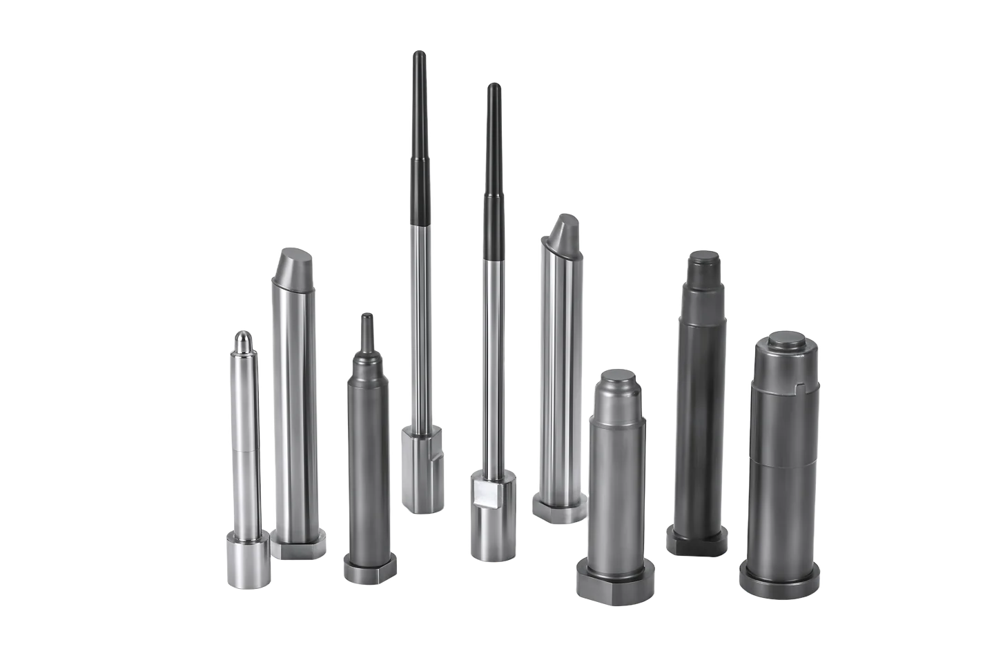
Library geometry examples · background removed / enhanced
01
New tooling
Current drawing revision, forming geometry, material and quantity.
02
Matched sets
Set identification, mating references and consistency requirements.
03
Replacement or change
Nominal dimensions, current mating condition, worn regions and intended changes.
05 / Your enquiry
Send the drawing.
Define the next step.
Share the forming detail, mating fit and the characteristics that matter. A clear technical brief gives the quotation a clear basis.
Review
Geometry, critical features & missing inputs
Clarify
Material, tolerances, finish & inspection
Quote
Confirmed scope, quantity & delivery basis
Lead time, open questions & project progress
Provide the target date and identify the component needed first. Feasibility, manufacturing route, supplier-supported treatments and inspection scope affect timing. Agree the quoted schedule and review any drawing changes before work continues.
Useful progress fields: drawing revision, material / treatment status, current operation, inspection status and dispatch plan. These are communication fields, not a live order tracker or a delivery guarantee.
Request a component review
What to send
- 2D drawing & available 3D model, with revision and units
- Material, hardness, treatment & surface zones
- Quantity, target date & new / replacement context
- Critical tolerances, datums & mating information
- Required inspection records & confidentiality needs
Need an NDA first? Start with the available non-confidential brief.
Before you send the drawing
Component choice, tolerances, replacement & inspection — FAQ
How do I choose the right component type?
Start with the molded feature and the part’s function. Pins usually form holes or internal details; thread components form thread geometry; neck rings address neck or closure profiles. If the name is unclear, send the drawing and assembly context.
Which tolerances can you achieve?
Feasibility depends on geometry, working length, material condition, finishing access and measurement method. Mark critical tolerances and datum references so they can be reviewed for the specific component.
Can you review a replacement component?
Provide the latest drawing revision, available mating-part information and the reason for replacement. Identify worn features and any requested changes. A sample can add context but does not define missing nominal dimensions.
What should I specify for materials and inspection?
Include the material grade, hardness, treatment and surface requirements. Identify the critical characteristics and required reports. Material and inspection documentation should be agreed as part of the project scope.