
THE DETAILS BEHIND EVERY CLOSURE
Precision Components
for Packaging and
Closure Molds
Thread. Seal. Surface.
Every detail starts with your drawing.
Custom cores, cavity inserts and mating components for packaging mold makers. Bring geometry, fit and finish into one coordinated review.
Drawing-based manufacture · Feature-specific inspection
FROM THE PACKAGING YOU SEE

Application concept · AI generated
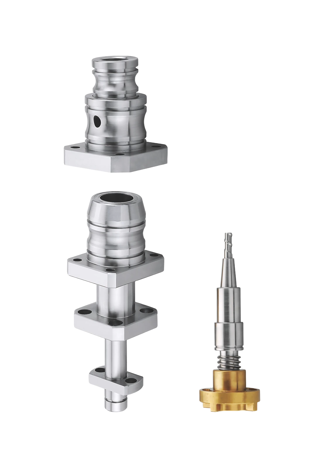
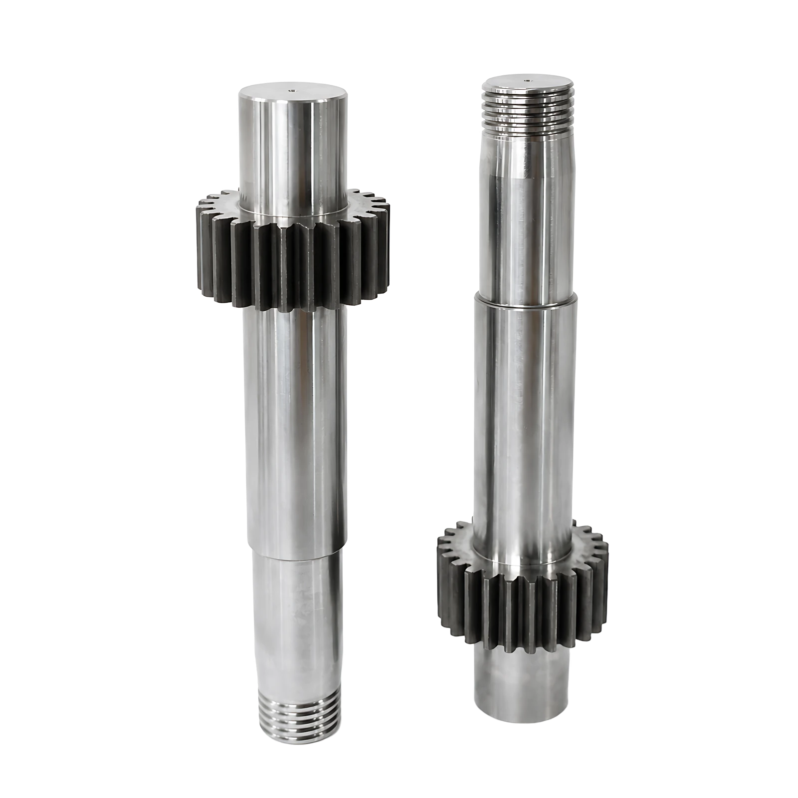
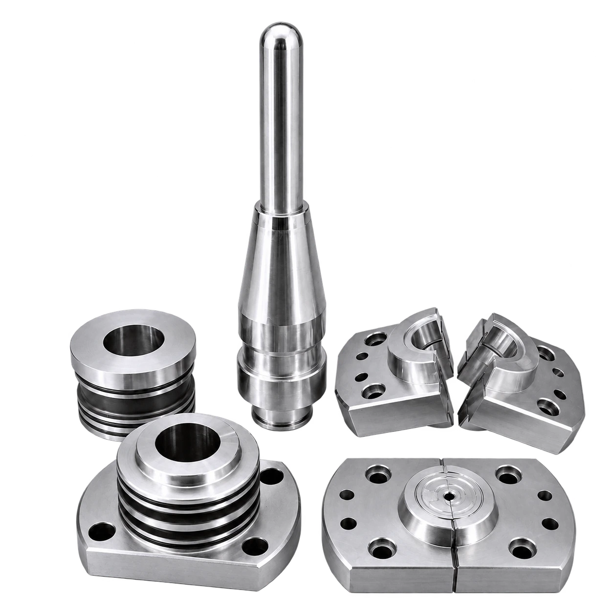
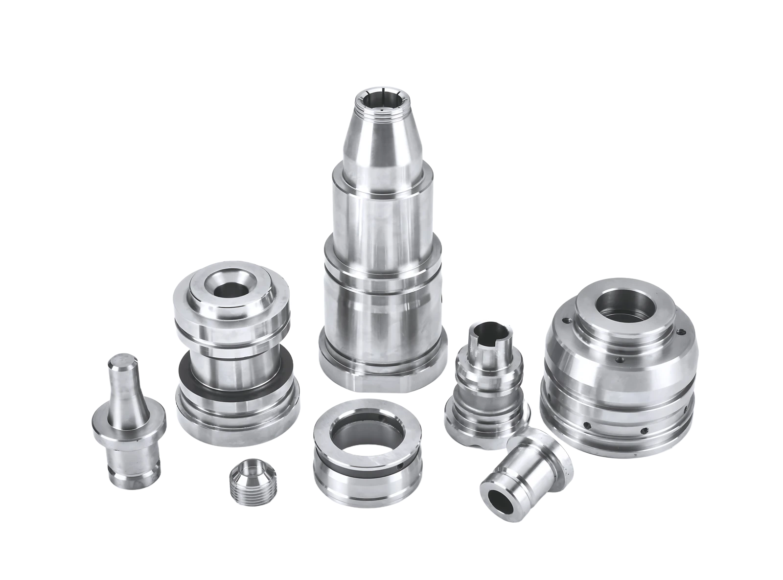
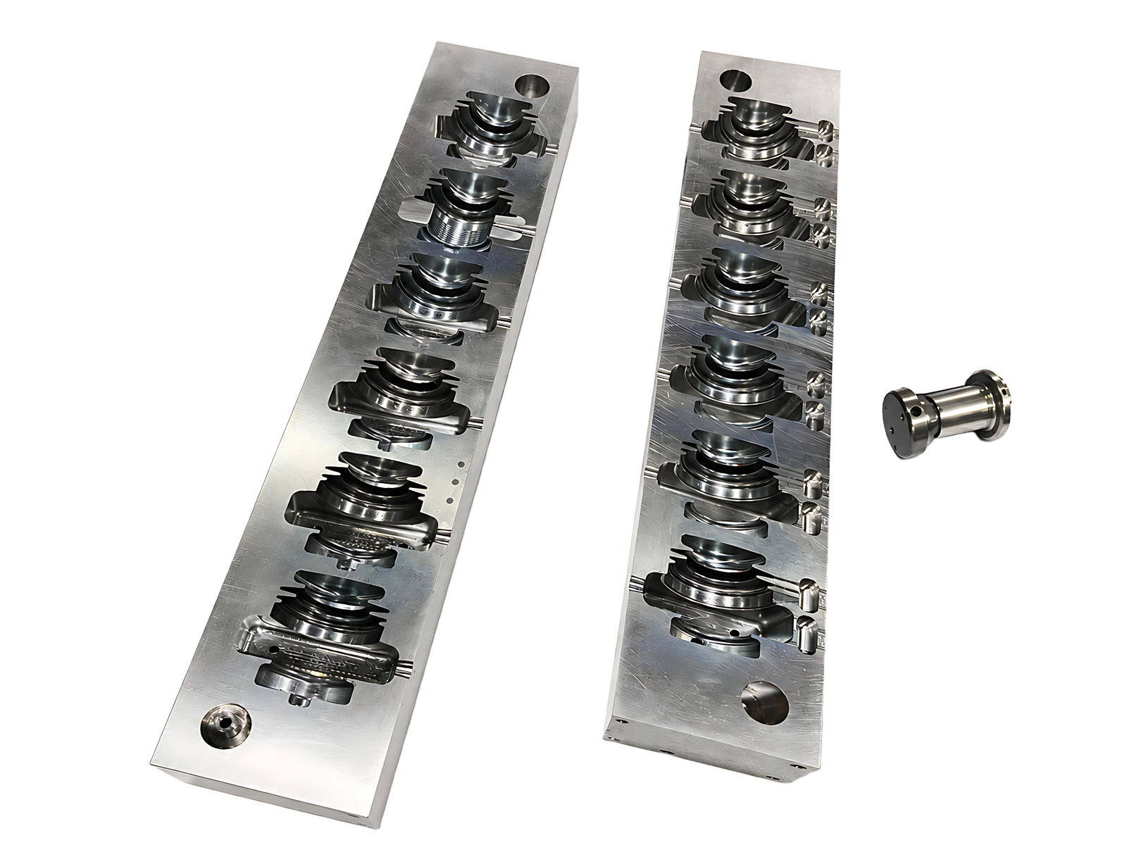
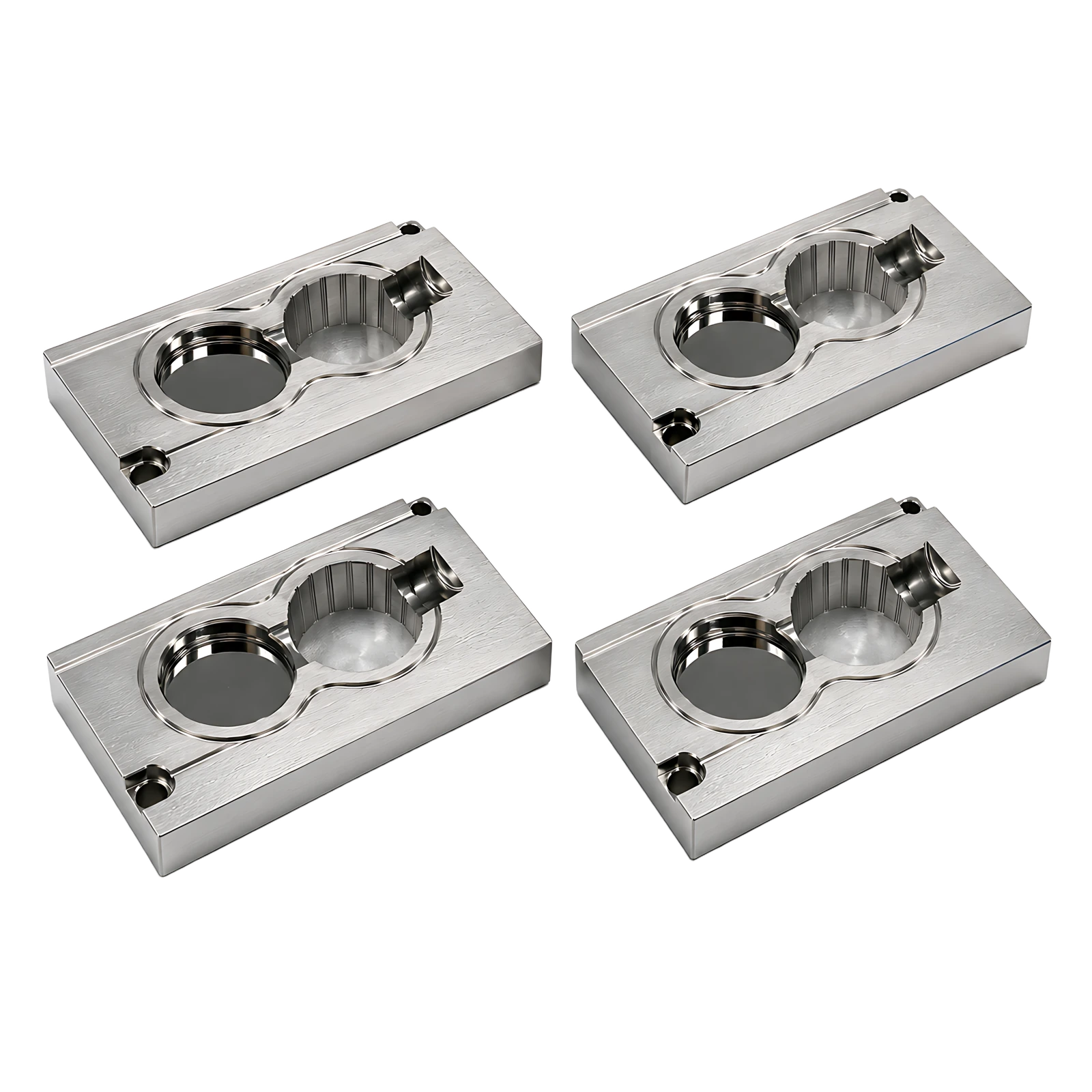
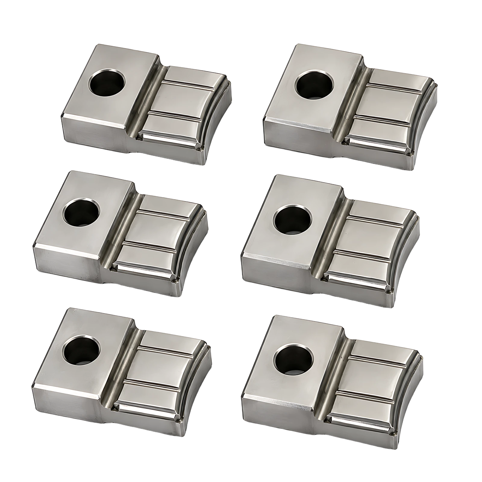
TO THE COMPONENT DETAILS WITHIN
01 / THE APPLICATION CONTEXT
Different closures.
Specific component demands.
Start with the molded feature, then define the component that forms it. Bottle caps, dispensing closures and cosmetic packaging share a need for clearly specified interfaces.
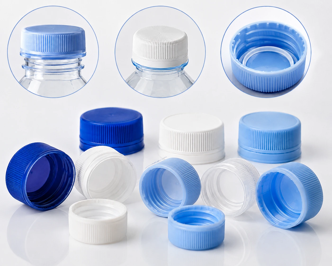
01 / BOTTLE CAPS
Thread & sealing geometry
Thread profile, release direction and the relationship to the mating neck.

02 / CAPS & CLOSURES
Split & mating interfaces
Parting lines, locating faces and assembly conditions that affect the fit.

03 / COSMETIC PACKAGING
Appearance & surface regions
Visible surfaces, texture transitions and edges that need to stay defined.
Application illustrations from the asset library; not photographs of verified SENLAN production outcomes.
02 / FIND YOUR COMPONENT SCOPE
The function comes first.
Choose a component family to see the information that makes a drawing review useful.
THREAD GEOMETRY / RELEASE / MATING DATA
Define more than
the nominal diameter.
For custom thread cores, the thread definition and release concept shape the review. Distinguish the molded thread from any mounting or drive thread on the component.
| Forming requirement | Profile, pitch or lead, starts, thread direction and runout. |
| Assembly context | Mating closure geometry, datum scheme and release direction. |
| Check to agree | Accessible profile checks and, where specified, a mating part or functional gauge. |
Using an unscrewing or collapsible mechanism? Include the assembly drawing so the component and mechanism scopes can be reviewed separately.
SPLIT FACES / LOCATION / ASSEMBLY
Review the surfaces
that work together.
For custom mold neck rings and split components, show the assembled condition. Identify which surfaces form the molded part and which locate the component in the mold.
| Forming requirement | Split line, formed profile, sealing regions and protected edges. |
| Assembly context | Both mating halves, locating features, assembly datums and relief areas. |
| Check to agree | Dimensional relationships, contact regions and assembled checks where specified. |
Identify matched pairs, replacement pieces and any interchangeability requirement separately.
FORMING SURFACES / ACCESS / FINISH
Separate the appearance
from the fitting surfaces.
For cosmetic packaging mold inserts, mark the visible molding areas, cooling interfaces and replaceable fitting surfaces. The finish should follow each region’s purpose.
| Forming requirement | Molding surface, viewing direction and finish or texture reference. |
| Assembly context | Insert location, cooling connections and neighboring component geometry. |
| Check to agree | Profile and fitting dimensions, surface boundaries and acceptance reference. |
A polished appearance does not establish a material grade, measured roughness or molding result.
Product photographs illustrate geometry. Packaging use, material and project association are established through the drawing review.
03 / COMPONENT DETAILS
Match the part to
the requirement.
Use these component examples to define the scope of your bottle cap mold inserts and packaging components. Material, treatment and acceptance criteria follow the approved drawing.
Threaded core components
| Feature | Thread profile and drive features |
| Drawing input | Thread section, release direction, runout |
| Route to review | Turning and restricted-feature machining |
| Check scope | Profile, datums and mating reference |
Stepped & flanged cores
| Feature | Forming diameter and mounting shoulders |
| Drawing input | Datum axis, shoulder faces, cooling features |
| Route to review | Rough / finish turning, local finishing |
| Check scope | Diameter relationships and axial location |
Split & round components
| Feature | Mating faces, location and circular profiles |
| Drawing input | Both halves, assembled view, protected edges |
| Route to review | Machine features, then finish fitting regions |
| Check scope | Contact areas and assembled dimensions |
Slider & fitting inserts
| Feature | Sliding faces and adjoining forming regions |
| Drawing input | Slide direction, shut-off region, clearances |
| Route to review | Datum machining, grinding and local EDM |
| Check scope | Fit, squareness and identified contact faces |
Cap mold insert examples
| Feature | Circular forming features and insert location |
| Drawing input | Part IDs, assembly layout and forming surfaces |
| Route to review | Feature-led machining and finishing sequence |
| Check scope | Feature position and inspection coverage |
Cavity blocks & inserts
| Feature | Pocket geometry and visible molding regions |
| Drawing input | Surface map, finish reference, transition edges |
| Route to review | Accessible machining, EDM where required |
| Check scope | Profile, fit and surface acceptance reference |
04 / MATERIAL REFERENCES
Materials for custom
mold components.
Material references from SENLAN component records. Final grade, condition and treatment are reviewed against your drawing.
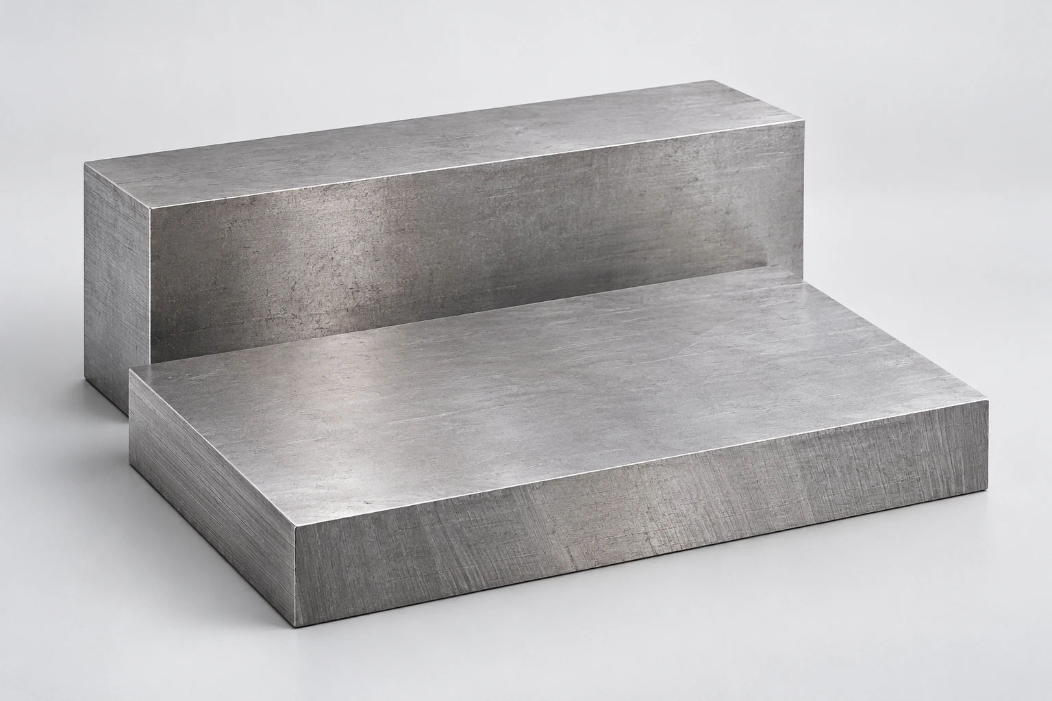
01
1.2083 ESR
Explore material
1.2083 ESR
RECORDED COMPONENT USE
Slider inserts
INCLUDE IN YOUR RFQ
Include the specified hardness and any nitriding requirements with the component drawing.
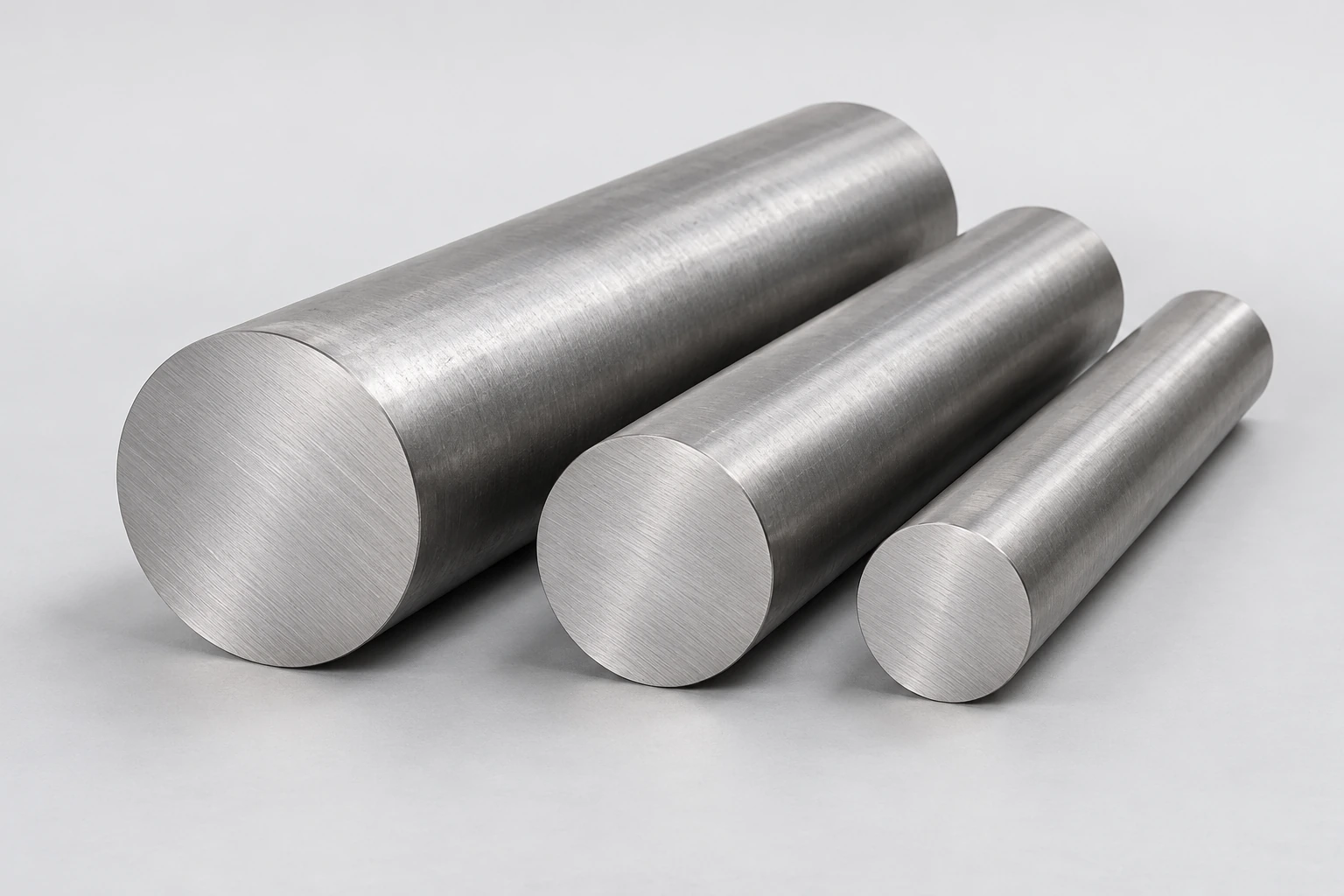
02
STAVAX ESR
Explore material
STAVAX ESR
RECORDED COMPONENT USE
Sleeve-pin components
INCLUDE IN YOUR RFQ
Confirm the exact grade, hardness requirement and surface-treatment scope.
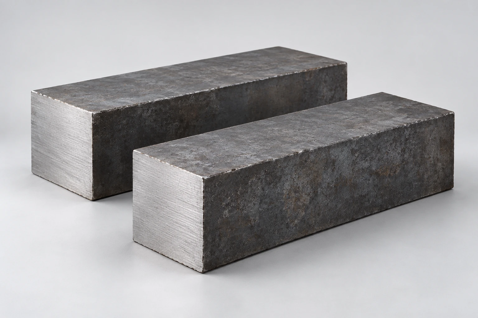
03
H13
Explore material
H13
RECORDED COMPONENT USE
Sleeve & cavity inserts
INCLUDE IN YOUR RFQ
Define the material condition, target hardness and any coating requirements by part number.
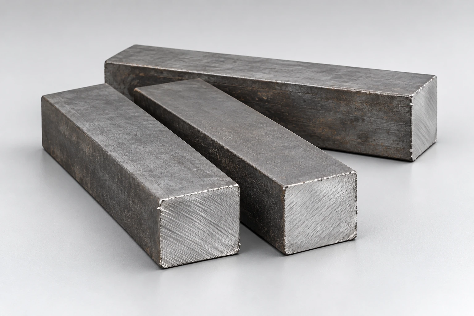
04
8407
Explore material
8407
RECORDED COMPONENT USE
Slide inserts
INCLUDE IN YOUR RFQ
Identify the material and hardness requirement for each component in the assembly separately.
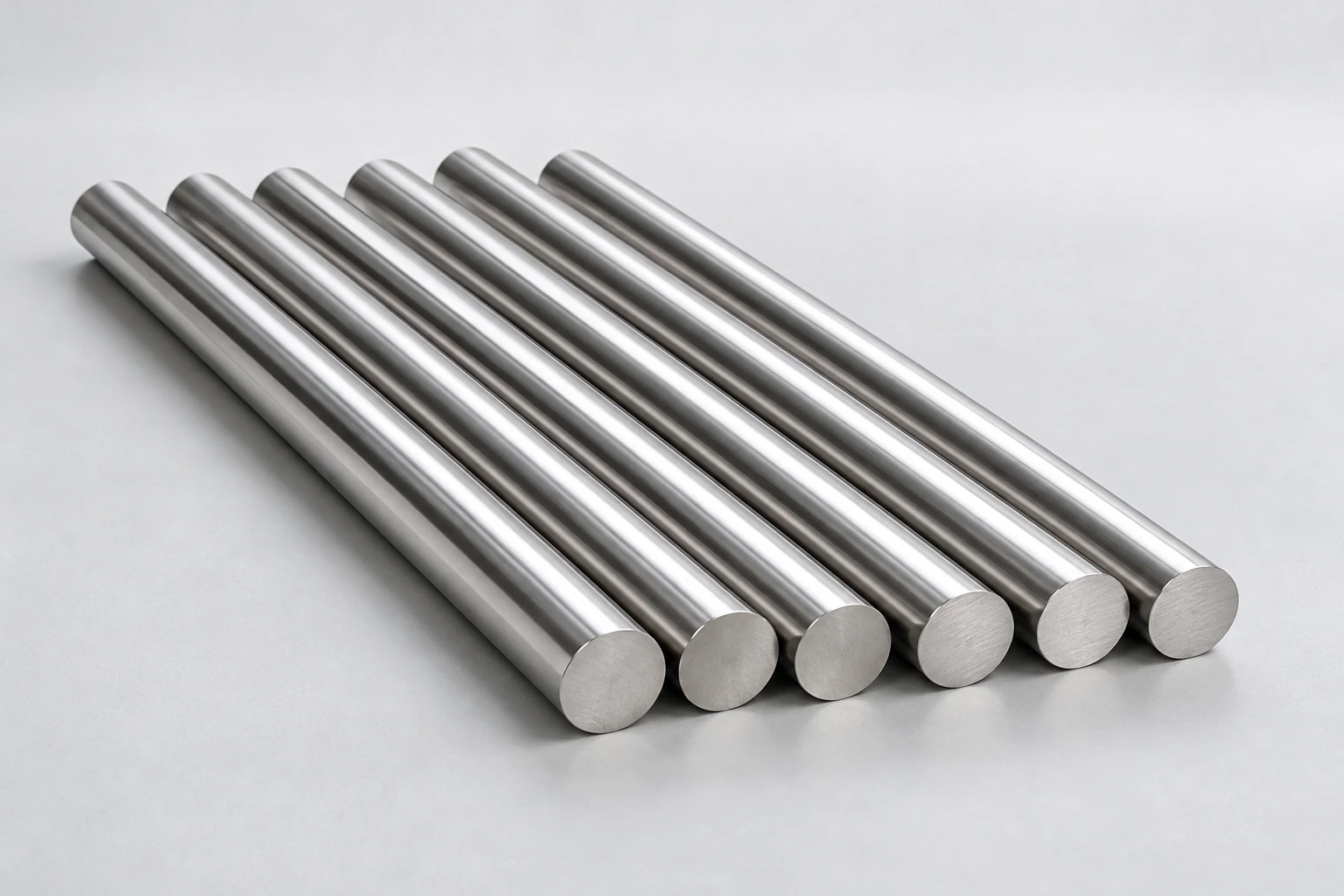
05
SKH51
Explore material
SKH51
RECORDED COMPONENT USE
Valve pins
INCLUDE IN YOUR RFQ
Provide the required hardness and any surface-treatment requirements alongside the pin geometry.
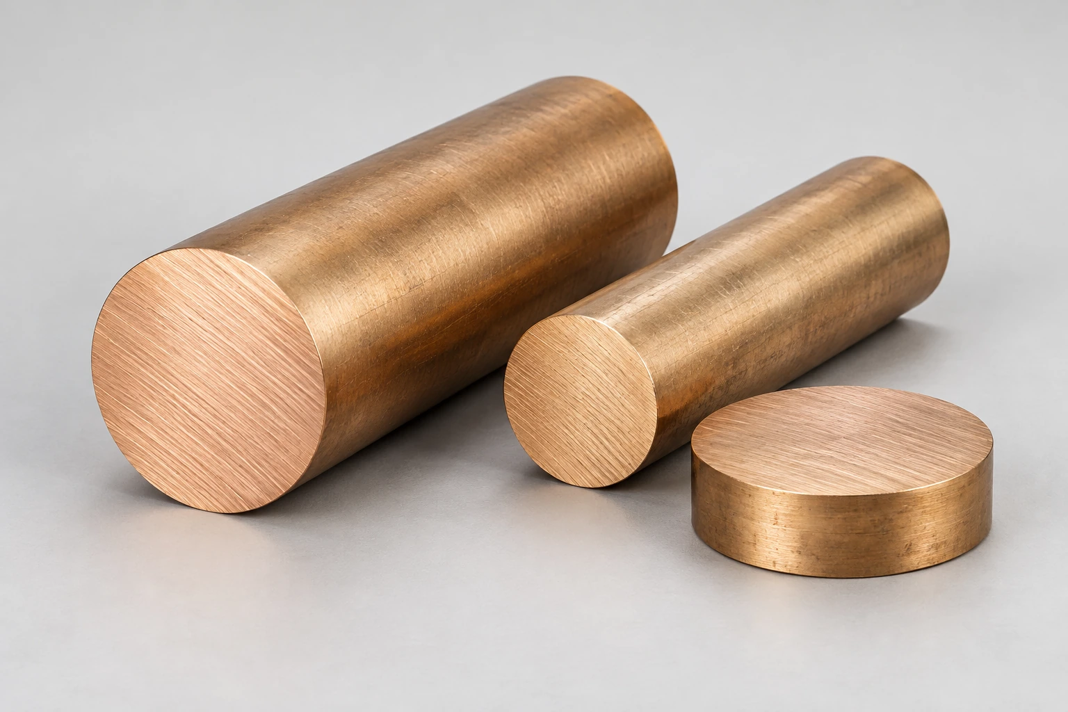
06
Beryllium copper
Explore material
Beryllium copper
RECORDED COMPONENT USE
Slide pins
INCLUDE IN YOUR RFQ
Confirm the exact alloy designation and supply condition before the material specification is finalized.
AI raw-stock concepts · Illustrative material forms, not photographs of SENLAN inventory or grade identification.
WORKING WITH SENLAN
Keep the important
details connected.
Bring the component drawing, process route and inspection brief into the same conversation.
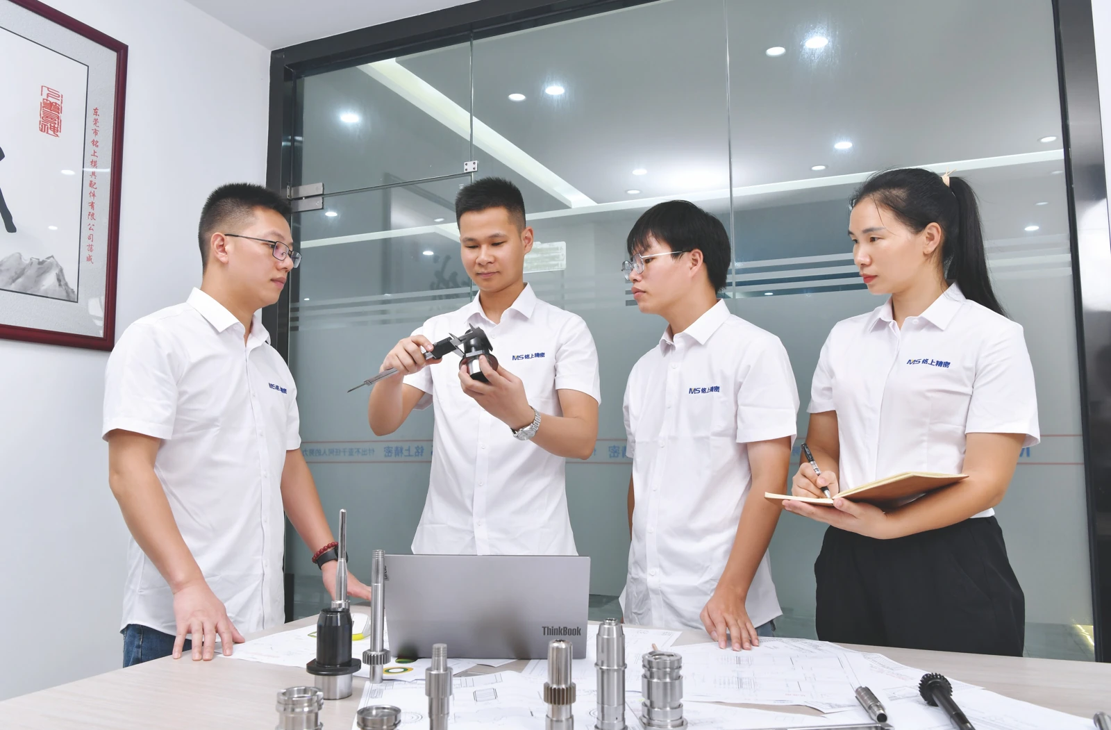
A review built around the component
Show the molded region, locating faces and assembled condition. A nominal size alone cannot describe all three.
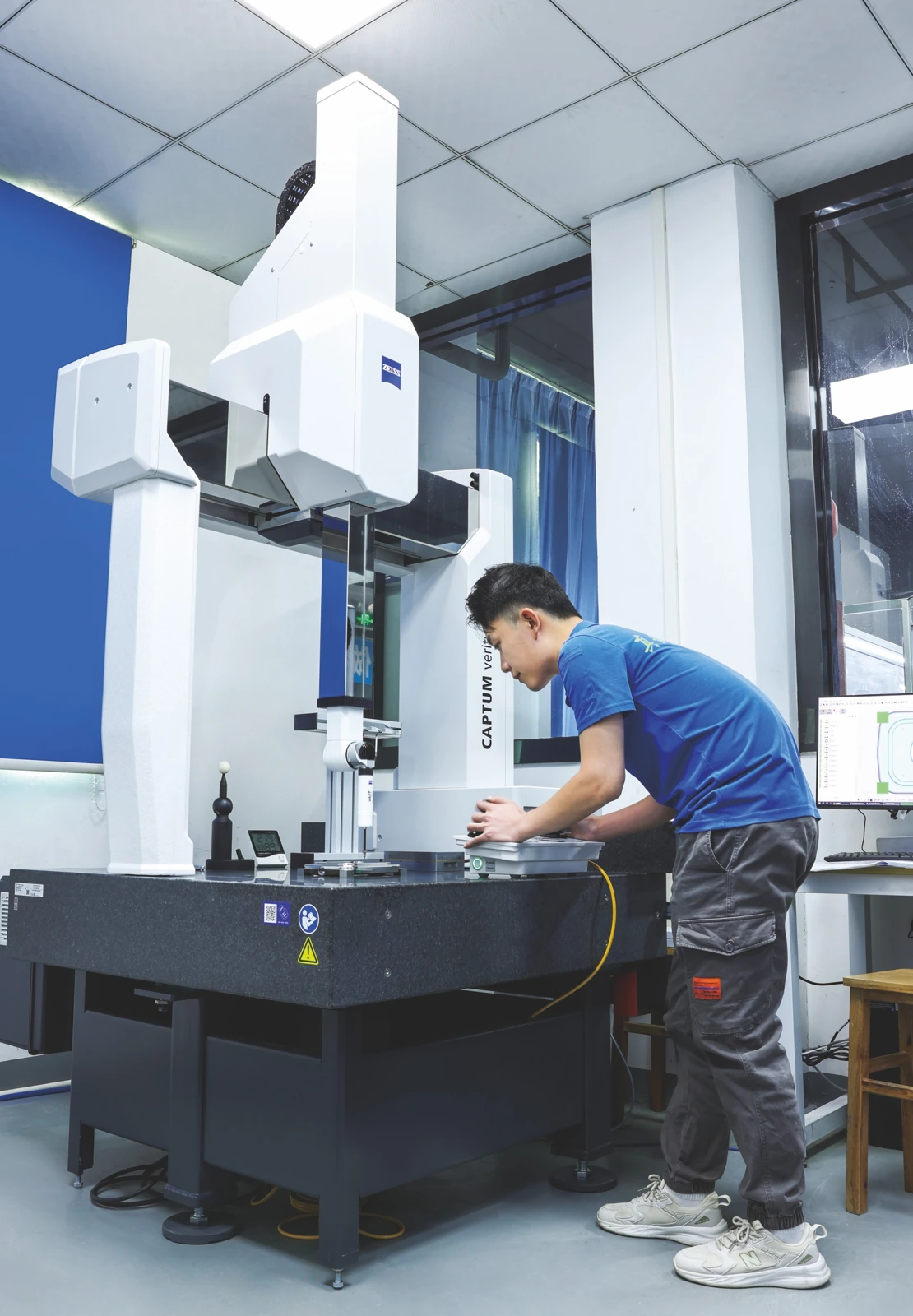
Inspection tied to the drawing
Agree datums, accessible features and report coverage. Select checks according to the feature and the acceptance requirement.
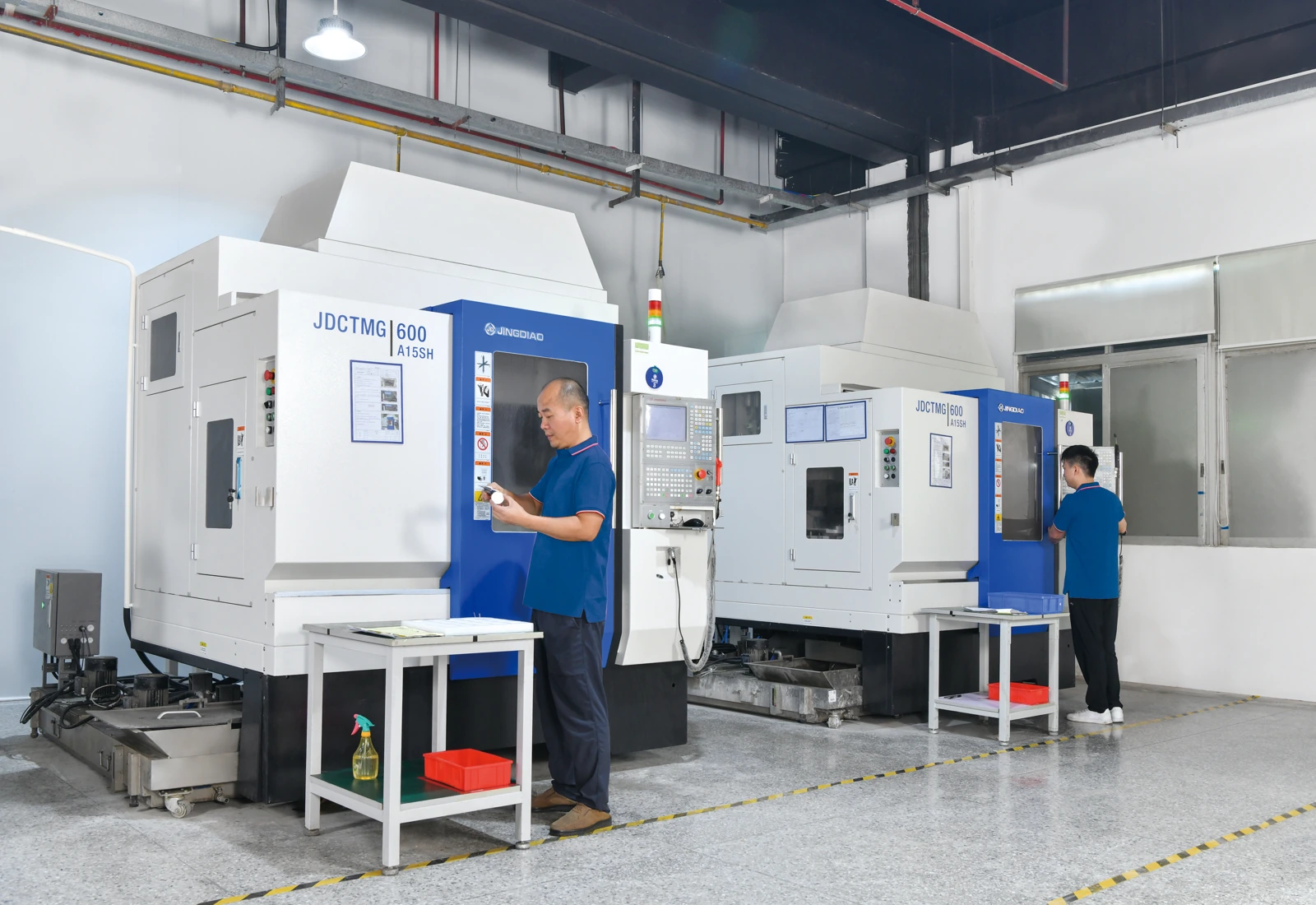
A deliberate process sequence
Identify setup datums and stock reserved for the next operation. Keep changes visible across the machining route.
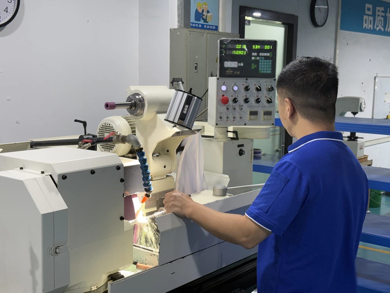
Surface requirements by region
Separate fitting surfaces from appearance areas. Protect specified edges and state where polishing or texture should stop.
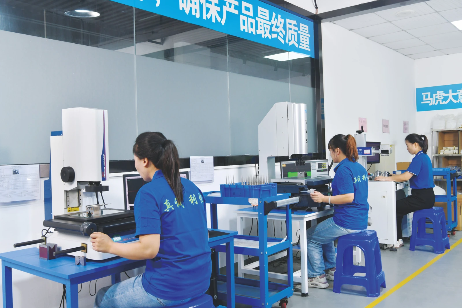
Clear criteria for related pieces
Identify part numbers, revisions and matched sets. Define what is checked individually and what is checked assembled.
PACKAGING MOLD COMPONENT CHALLENGES
Small details.
Connected decisions.
A closure thread, a split face and a polished cavity each need a different brief. Problems arise when the finish requirement obscures a fitting dimension, a revised piece is compared with an earlier mating part, or an inspection method cannot reach the specified feature.
THREE QUESTIONS FOR YOUR COMPONENT SUPPLIER
Make the review specific.
01
Is the supply boundary clear?
Separate the individual component from the complete mold or release mechanism.
- Part numbers, revisions and quantities
- Mating geometry and scope of supply
- Customer-supplied or external operations
02
Do the requirements survive each operation?
Follow the functional feature through machining, treatment and finishing.
- Datums and machining stock
- Finish boundaries and protected edges
- Acceptance after the final operation
03
What evidence will be supplied?
Connect each acceptance requirement to an agreed check and reporting scope.
- Accessible dimensional or profile checks
- Identification of pieces and matched sets
- Requested treatment and inspection records
LET’S REVIEW YOUR COMPONENT
Send the drawing.
Show the interfaces.
Share the geometry and assembly context. Together, define the manufacturing and inspection scope for your packaging mold components.
Start with the information available in the existing RFQ form.
Your drawing-review checklist
0 / 4 ready
Use this checklist to prepare your inquiry. Your selections stay in this browser session and do not submit a request.
PRACTICAL QUESTIONS
Before you
send the RFQ.
Details that help turn a component drawing into a clear review scope.
How should thread and sealing requirements be supplied?
Provide the thread profile and section, pitch or lead, starts, direction and release concept. Identify the sealing land and include mating geometry or an agreed reference. Separate mold-component characteristics from molded-part requirements.
How do I specify different surface areas?
Use labeled regions on an annotated drawing. Assign forming, textured, polished and fitting areas their own references. Show transition boundaries and edges that must not be rounded. Retain the stated standards and acceptance conditions for A1–A3 and VDI references.
What is needed for multi-piece and fitting checks?
Provide mating geometry, datums, the assembled condition and quantity by part number. Identify matched sets, spares and any interchangeability requirement. Agree inspection coverage, identification and report format before manufacture.