
THE DETAILS BEHIND LABORATORY CONSUMABLES
Precision Components
for Medical and
Laboratory Molds
Fine profiles. Clear interfaces.
Every detail starts with your drawing.
Custom core pins, cavity inserts and mating components for medical mold makers, laboratory consumables mold makers and in-house toolrooms.
Drawing-based manufacture · Feature-specific review
END PRODUCT
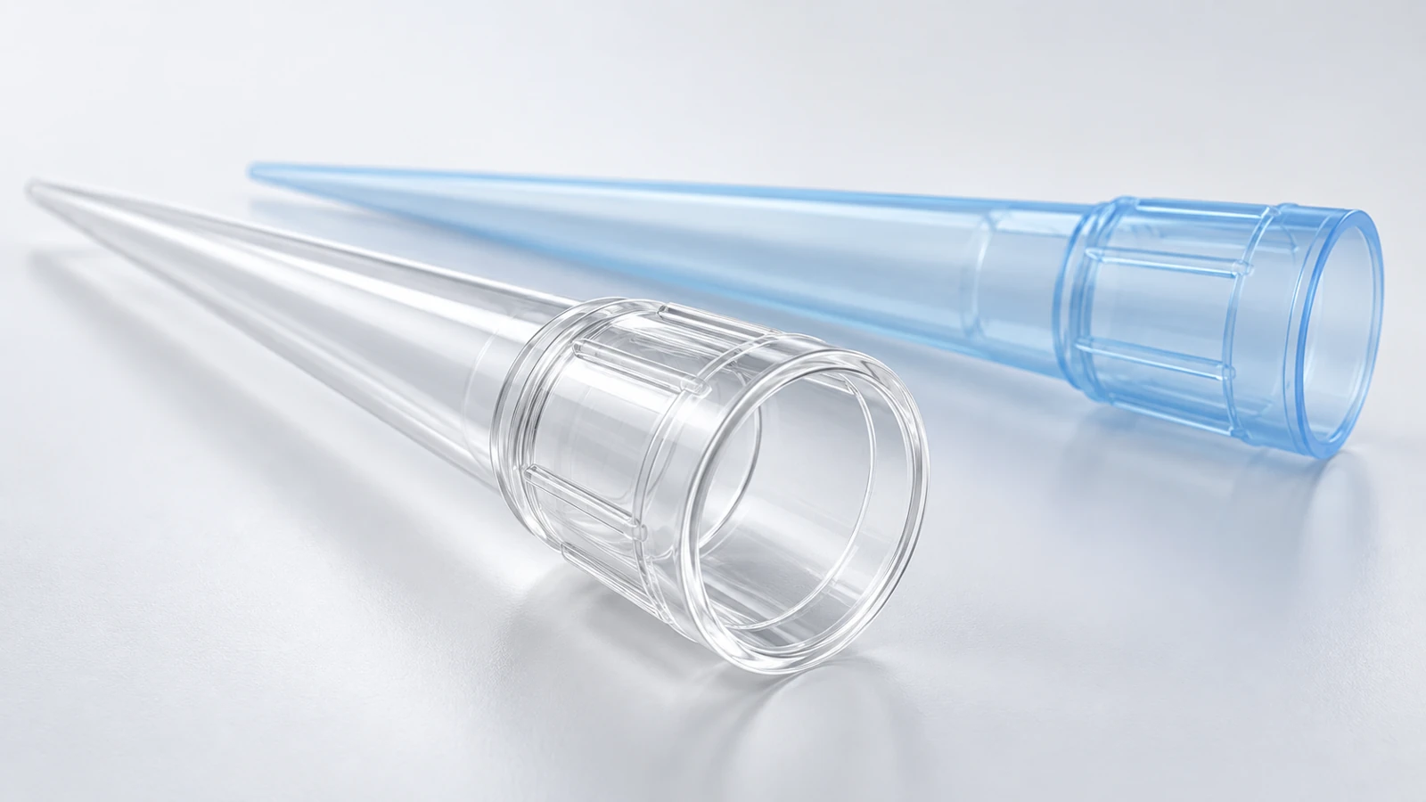
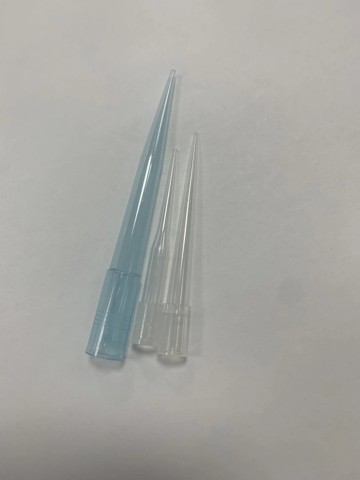
Pipette tips
For laboratory liquid handling
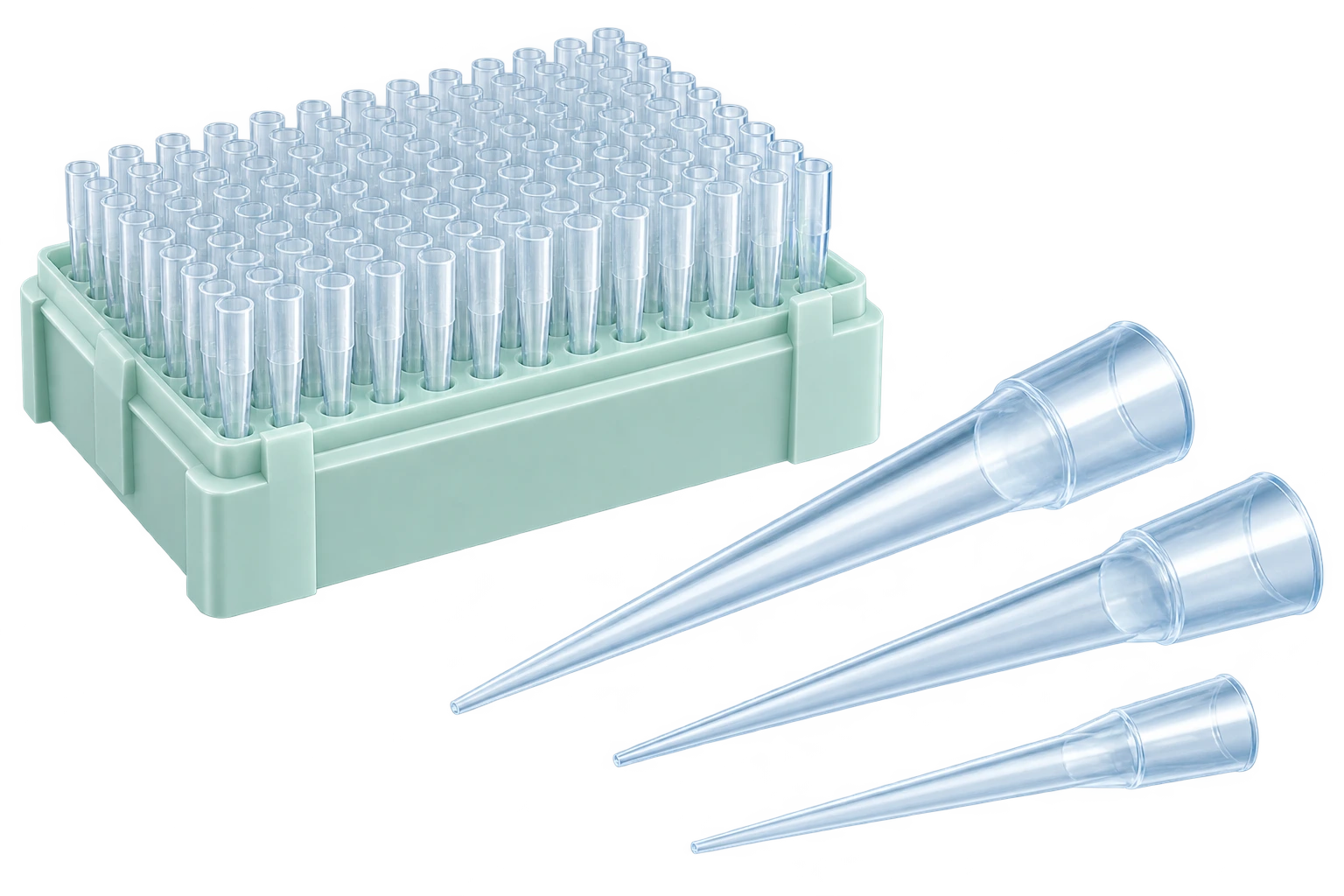
THE TOOLING BEHIND THE TIP
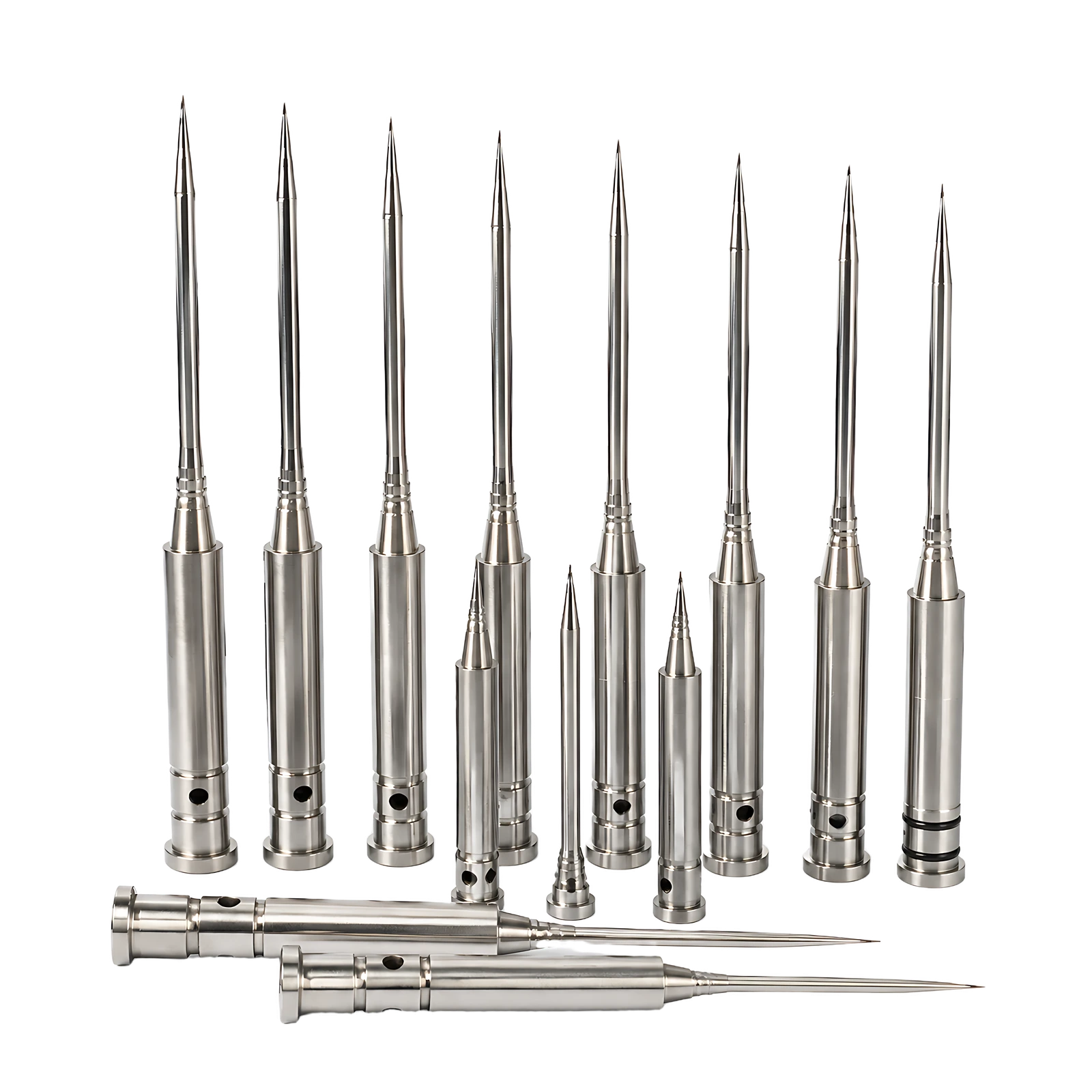
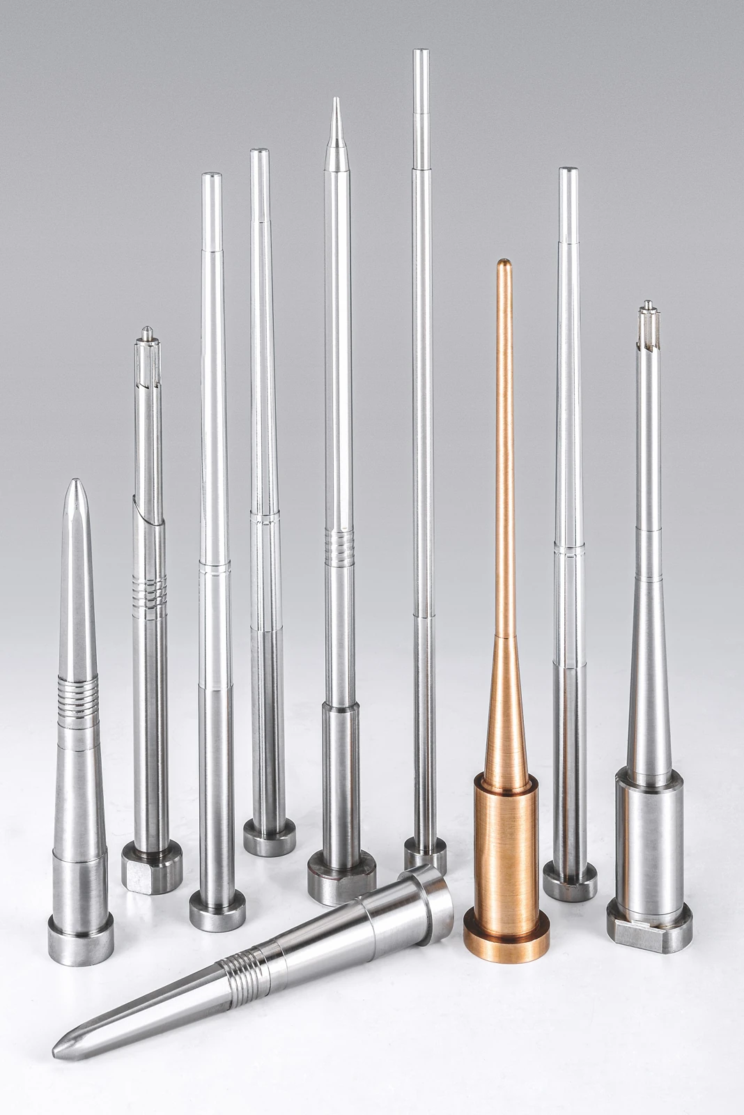
Core pins
Form the internal taper
Library image · AI enhanced
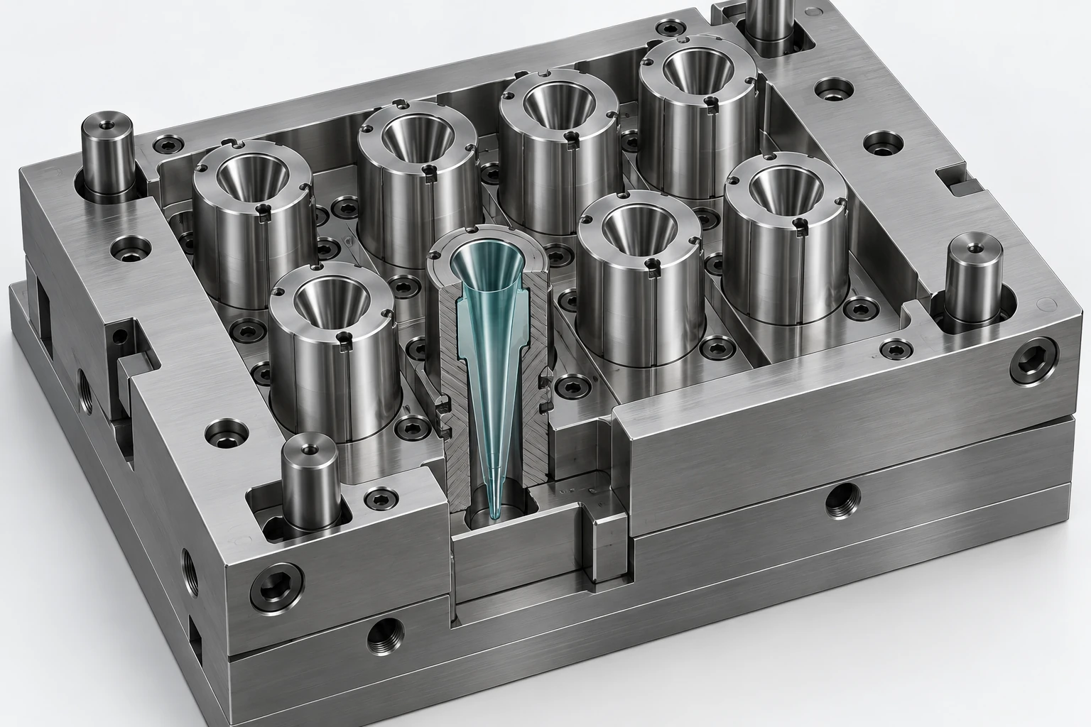
Cavity inserts
Form the outer profile
AI assembly concept
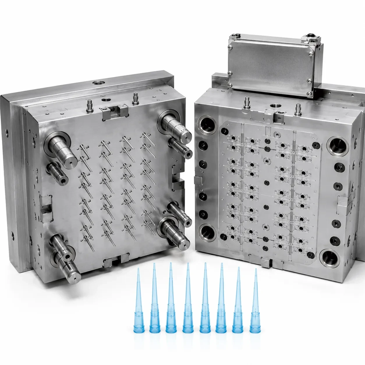
Mold assembly
Bring the tooling together
Library application reference
Component and mold views illustrate the application relationship.
01 / APPLICATION & FUNCTION
Small molded features.
Specific tooling requirements.
Start with the feature the component forms. Define the part geometry, the mating interfaces and the inspection requirement together.

FORMING GEOMETRY
Internal taper & slender profile
Describe the working profile, supported length and forming end. Relate each feature to the locating surfaces.
MATING INTERFACES
Attachment & mating regions
Show the assembled condition and contact areas. Define the fit separately from the appearance of the molded part.
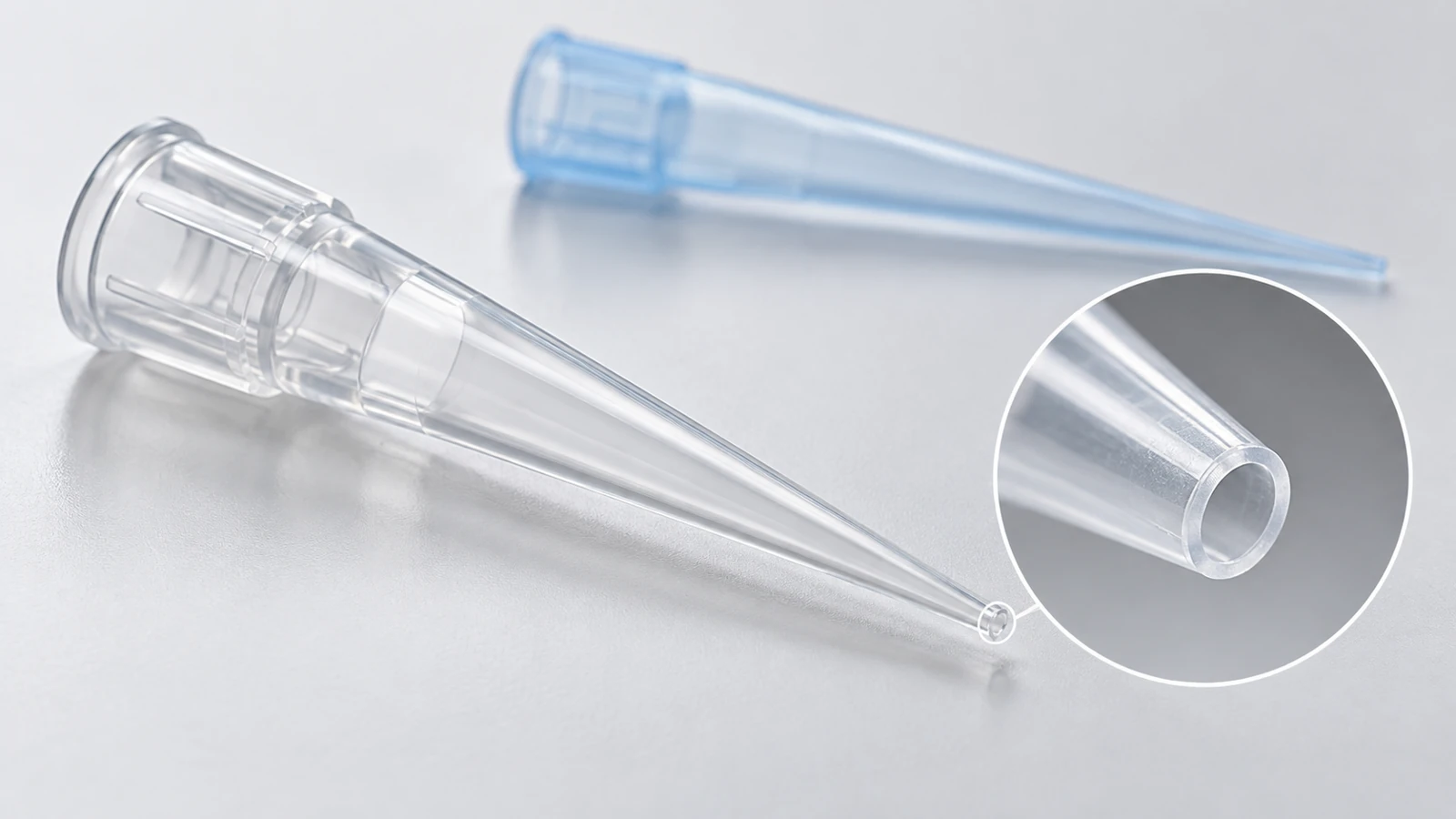
FINE FORMING DETAILS
Outlet & local transitions
Identify the end land, transition radii and edges to preserve through machining and finishing.
Supply scope
Custom tooling components for mold builds, replacements and modifications. Mold and consumable images provide application context.
Application visuals · AI concepts
02 / FROM MOLD TO MOLDED PART
See the assembly.
Understand the component.
The pipette-tip mold reference connects core pins, cavity inserts and stripping interfaces to the laboratory consumable they help form.
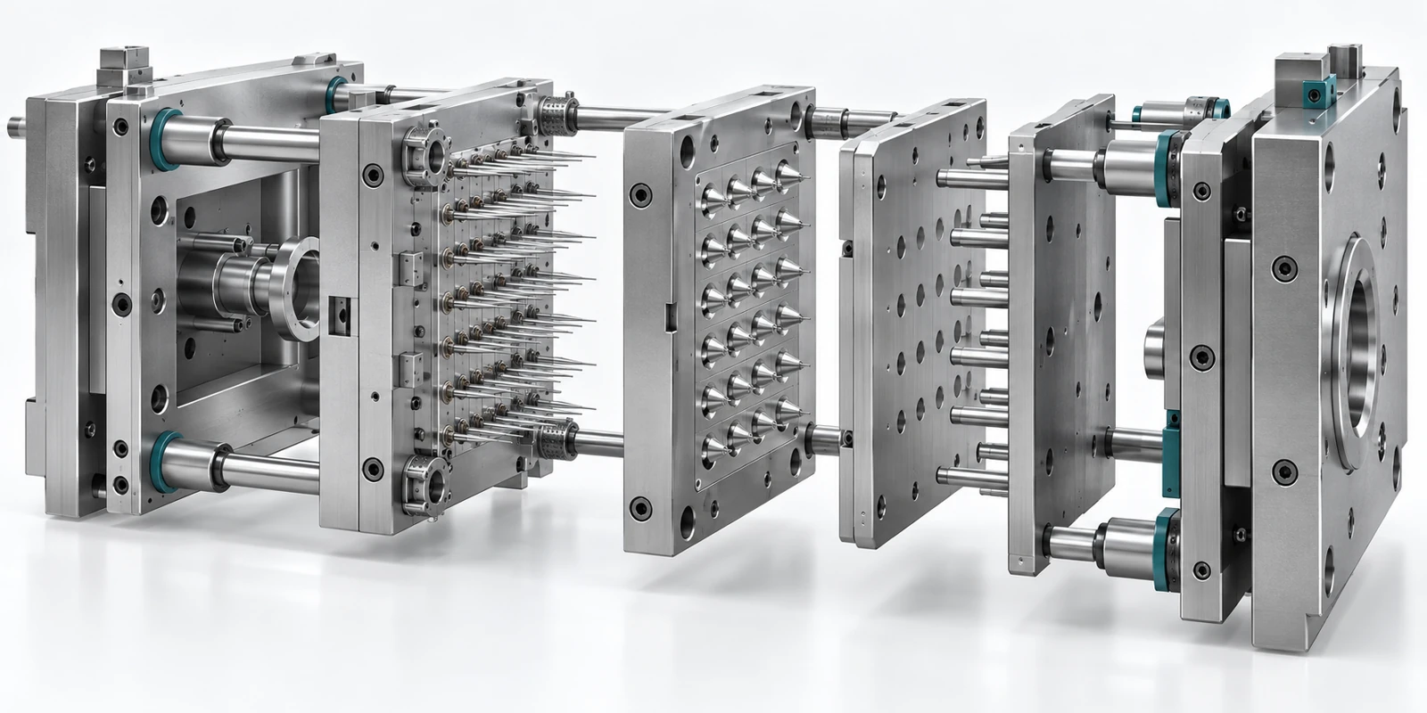
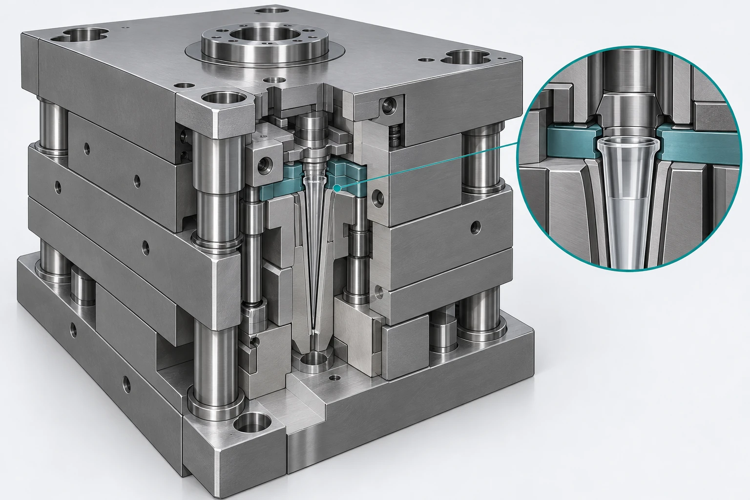
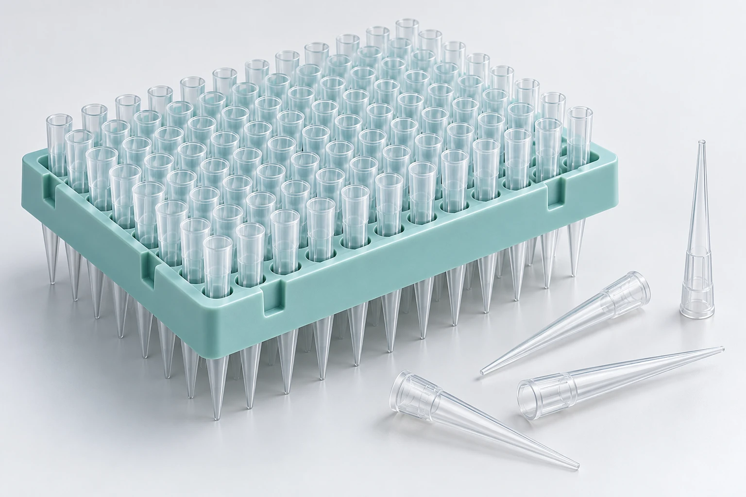
AI concepts of the assembly, forming interfaces and molded application. Actual supports, plate layout and interfaces depend on the mold design.
03 / FIND THE COMPONENT FUNCTION
The function comes first.
Choose a component family to see which geometry, process inputs and checks belong in your drawing review.
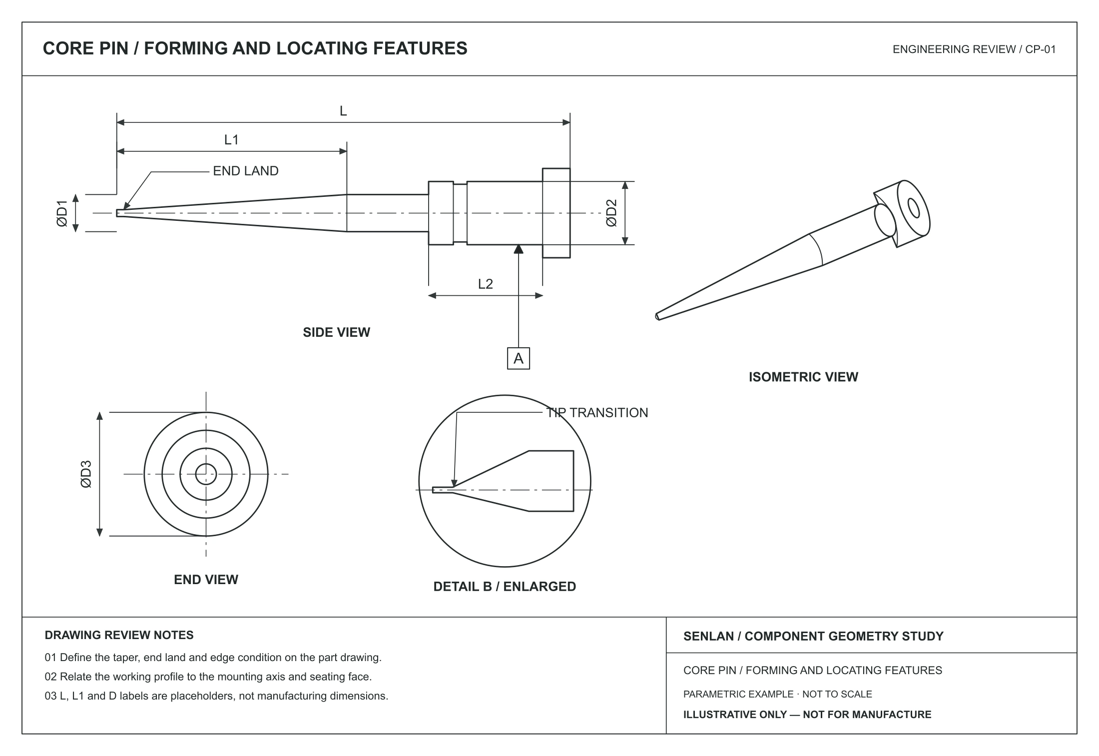
Technical concept · not a customer drawing · not to scale
CORE PINS & FORMING ENDS
Slender geometry.
Related references.
A core pin defines internal forming geometry. Its working profile must be reviewed together with the mounting and support arrangement.
| Forming profile | Taper, local radius, end land and edge condition. |
| Support & location | Working diameter, unsupported length, locating diameter and seating shoulder. |
| Process review | Turning, grinding and local finishing according to geometry, access and condition. |
| Checks to agree | Profile, diameter and specified straightness or runout relative to drawing datums. |
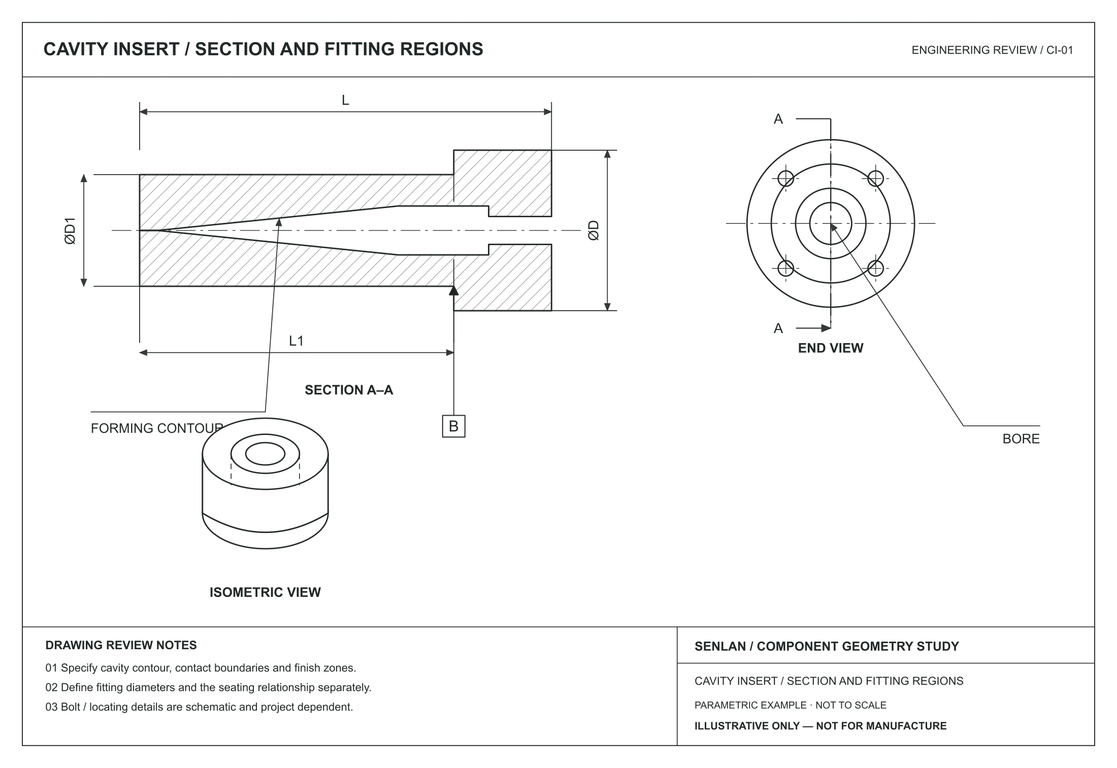
Technical concept · not a customer drawing · not to scale
CAVITY & MOLD INSERTS
Forming surfaces.
Defined fitting regions.
Cavity inserts form external contours and local molded details. Specify the cavity geometry separately from locating, seating and shut-off features.
| Forming profile | Cavity contour, local steps and polymer-contact regions. |
| Fit & shut-off | Mating faces, seating geometry and intended contact boundaries. |
| Process review | Machining and EDM suitability, electrode access and finish requirements. |
| Checks to agree | Accessible dimensions, profile and fit requirements after the final operation. |
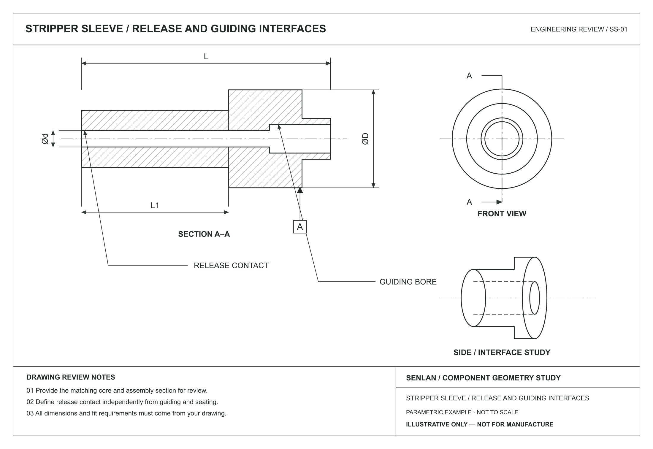
Technical concept · not a customer drawing · not to scale
STRIPPER & MATING INTERFACES
Release interfaces.
Clear mating conditions.
Stripping and sleeve interfaces depend on the mold design. Share the assembly section so the contact zones and support relationship can be reviewed.
| Working function | Release contact, guiding region and polymer-contact surfaces. |
| Interface geometry | Bore, outside diameter, seating face and mating component. |
| Process review | Feature access, datum transfer and protected fitting surfaces. |
| Checks to agree | Individual dimensions and specified checks in the assembled condition. |
04 / A CLOSER LOOK
Carry the critical detail
through every operation.
Separate the functional feature from the way it is held, machined and measured. These views make the drawing review more specific.
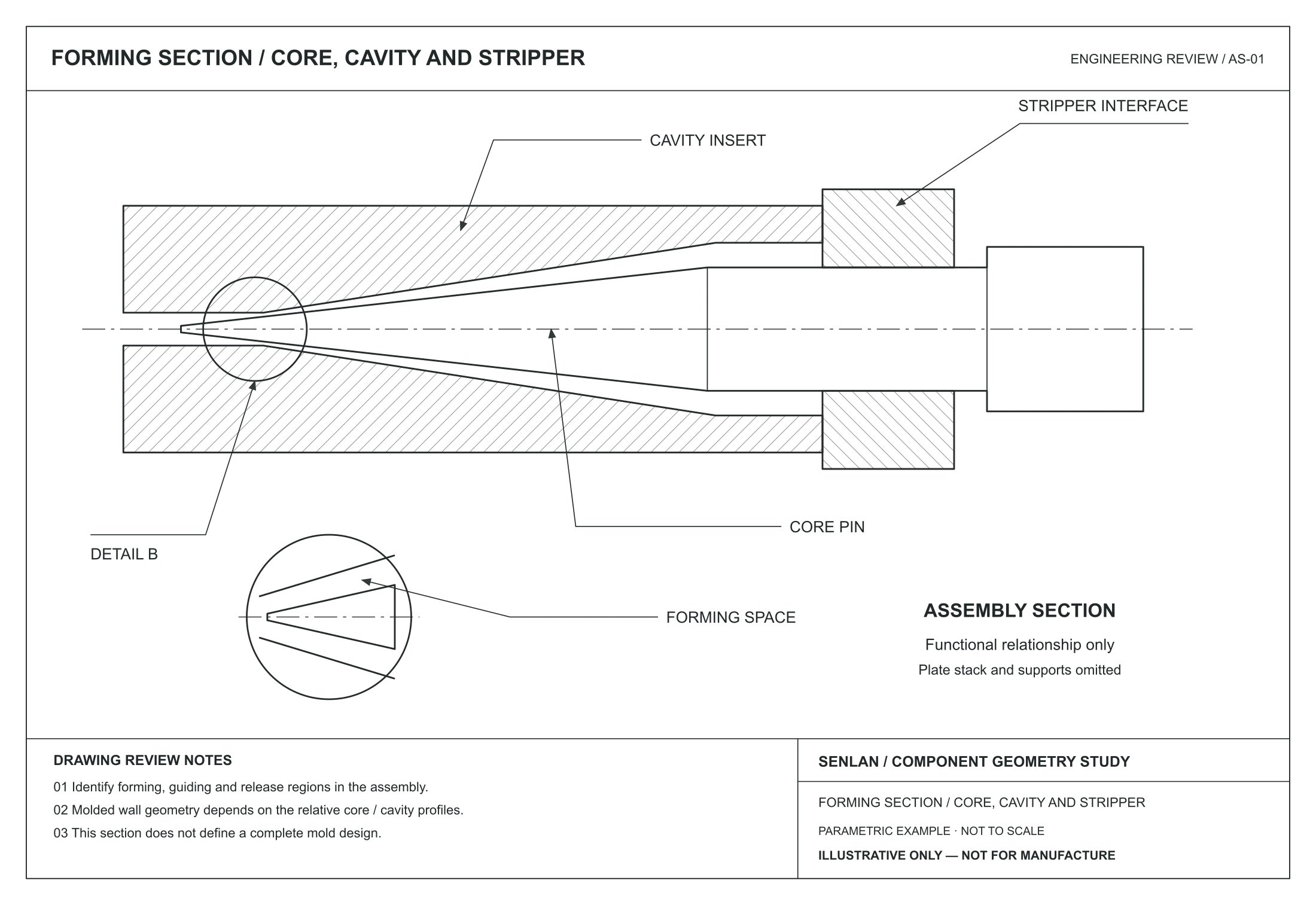
Illustrative engineering drawing
01 / FEATURE REVIEW
Core-to-cavity relationship
Show the forming section and the surfaces that must remain related.
| Define | Core profile, cavity contour and assembly references. |
| Review | Support and access at the working end. |
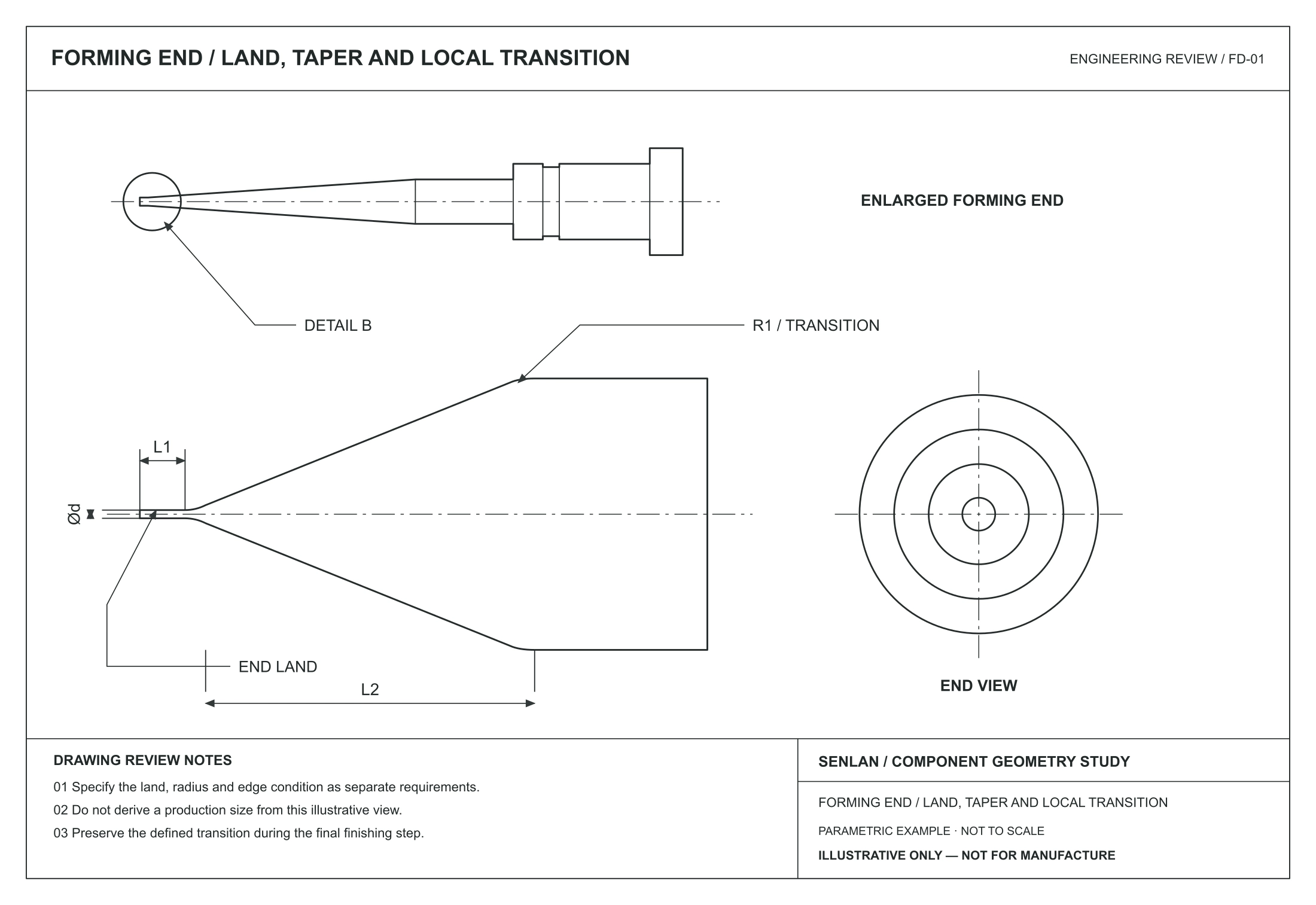
Illustrative engineering drawing
02 / FEATURE REVIEW
Fine forming ends
Describe the end detail in its own enlarged drawing view.
| Define | End land, local radii and transition boundaries. |
| Protect | Critical edges during final finishing. |
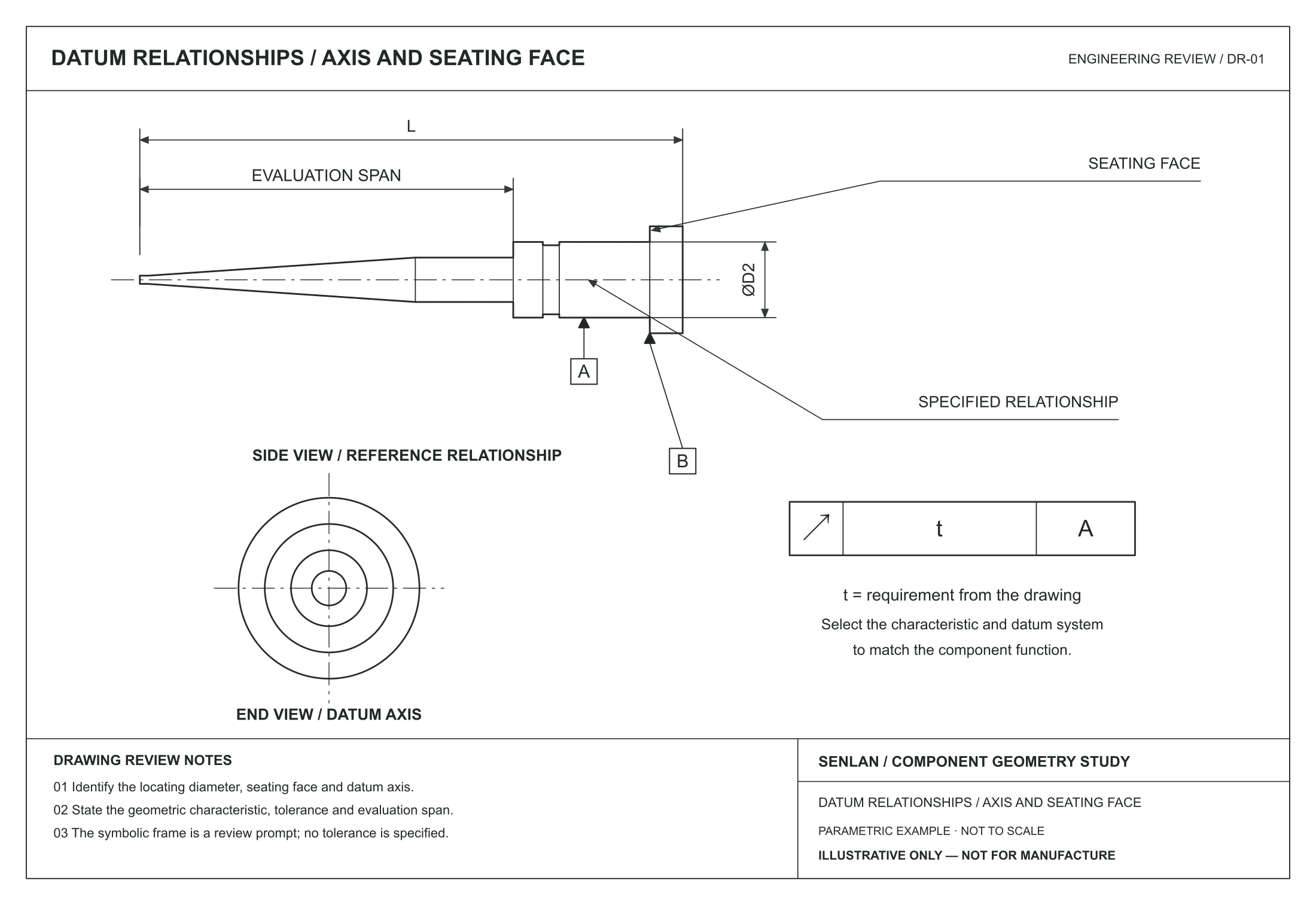
Illustrative engineering drawing
03 / FEATURE REVIEW
Locating & seating features
Relate the slender working profile to the features used for setup.
| Define | Locating diameter, seating face and datum axis. |
| Check | Specified relationships over the evaluation span. |
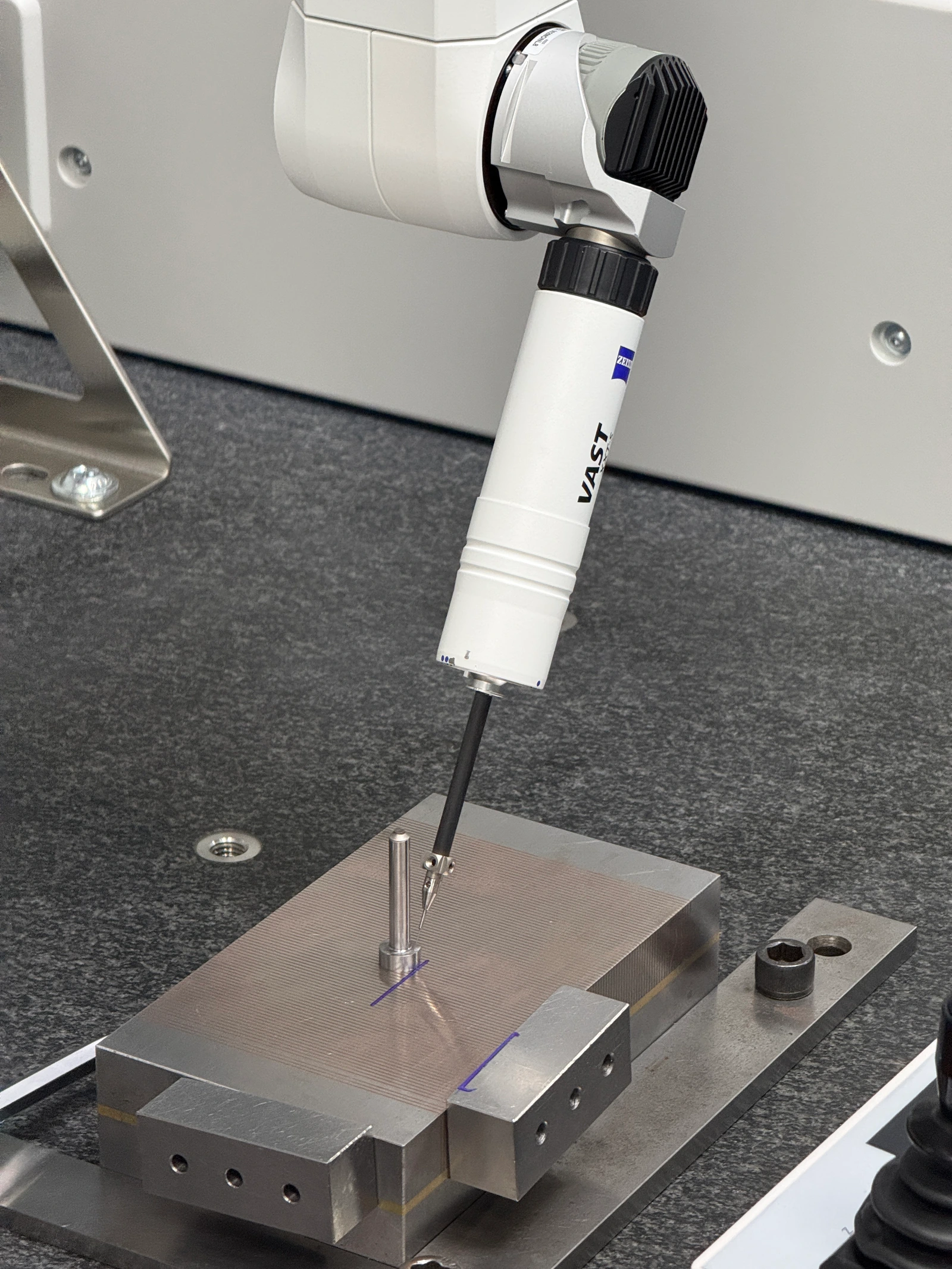
04 / FEATURE REVIEW
An inspection plan by feature
Choose the measurement method around access and required uncertainty.
| Define | Measurement locations and part support. |
| Report | Critical characteristics, method and revision. |
05 / MATERIAL & FINISH BRIEF
The grade is one input.
The condition completes the brief.
Keep material, hardness, functional surfaces and documents connected to the component drawing. Hover or tap a card for the details.
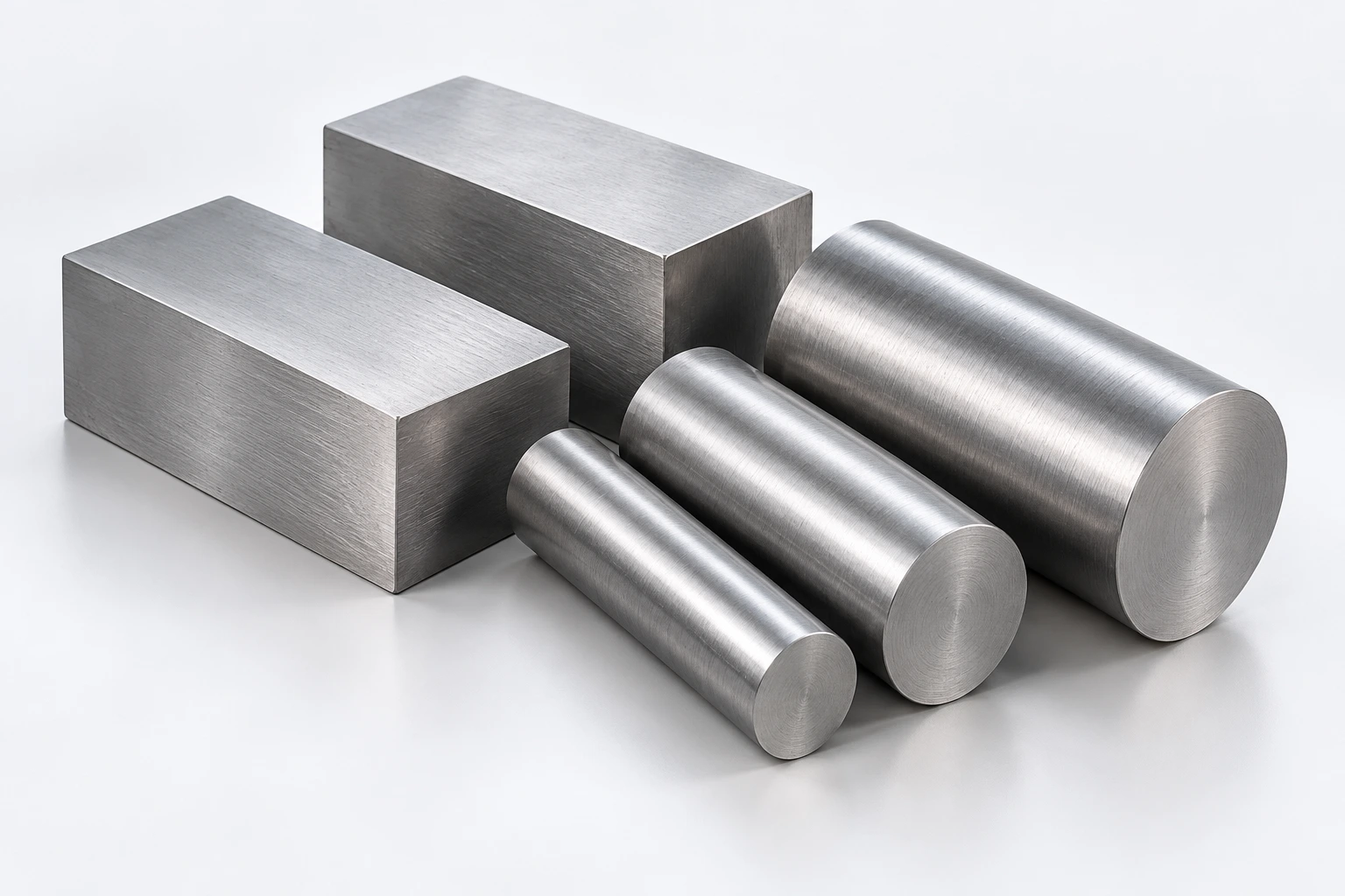
01
STAVAX
Explore requirements
STAVAX
RECORDED MATERIAL REQUIREMENT
Pipette-tip component record
INCLUDE IN YOUR RFQ
A historical application record specifies STAVAX for core pins, cavity inserts and stripper inserts. Supply the exact grade and condition in the current RFQ.
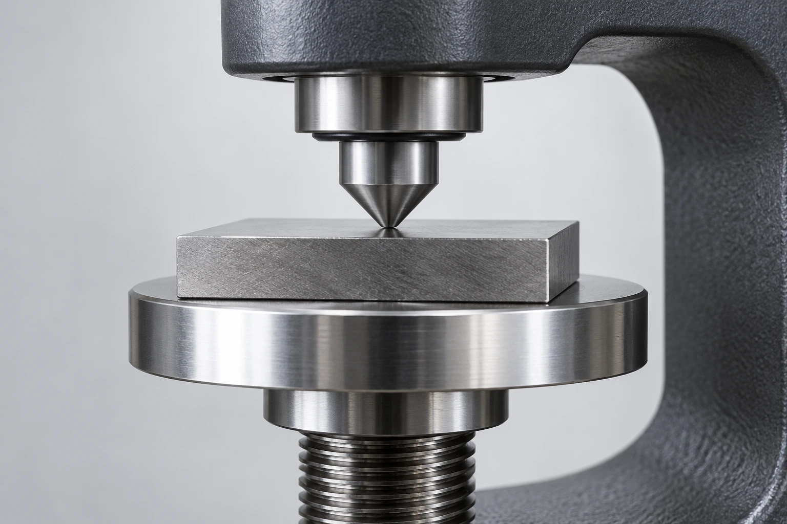
02
Hardness & condition
Explore requirements
Hardness & condition
SPECIFY THE FINAL CONDITION
Requirement and verification
INCLUDE IN YOUR RFQ
State the required hardness and the stage at which it applies. Agree heat-treatment scope and records; heat treatment is listed as an external operation.
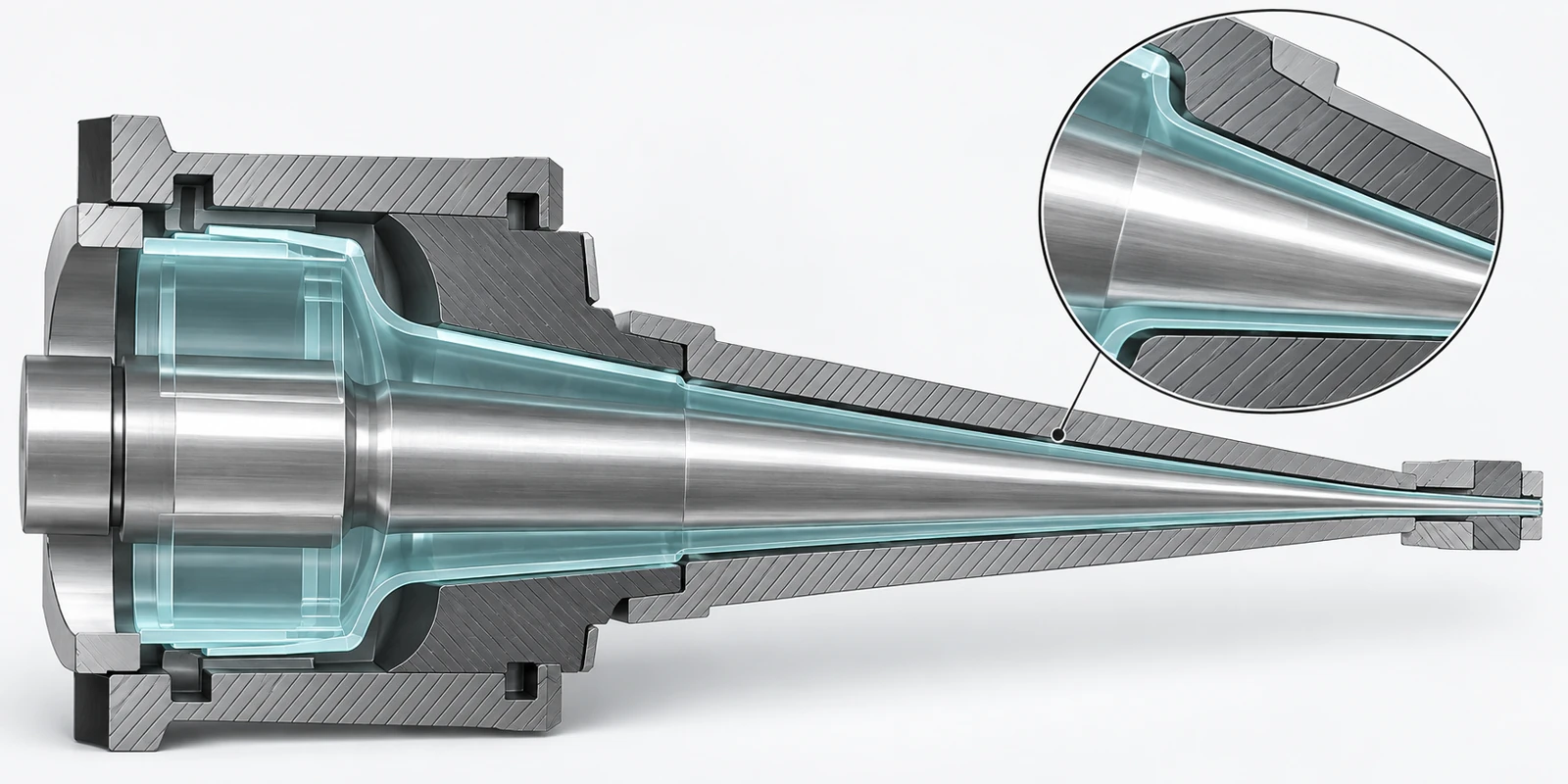
03
Surface regions
Explore requirements
Surface regions
MAP THE FUNCTIONAL AREAS
Finish without losing the feature
INCLUDE IN YOUR RFQ
Separate forming, locating and other surfaces. Identify the finish reference, transition boundaries and edges that must remain intact.
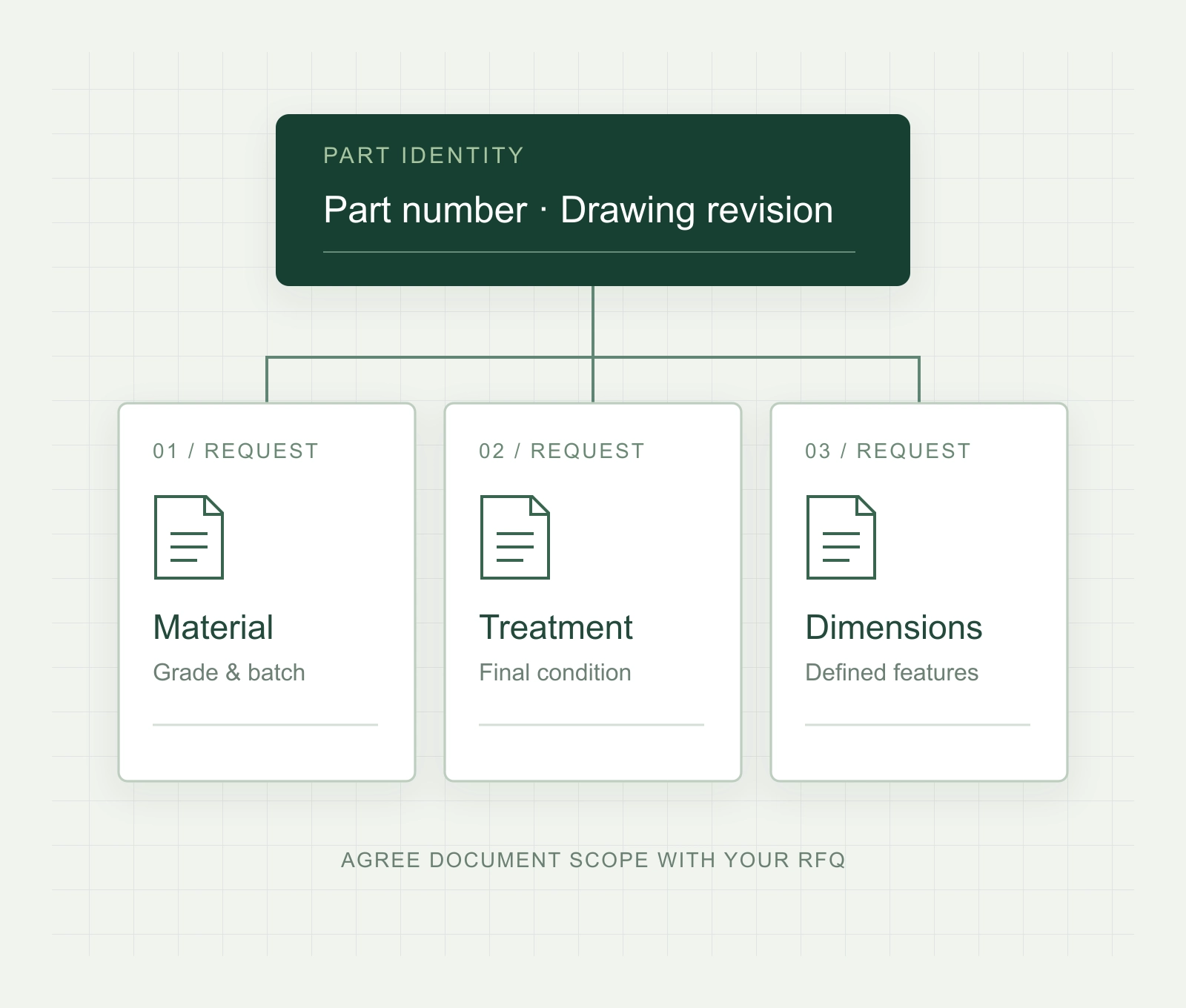
04
Documents & IDs
Explore requirements
Documents & IDs
CONNECT THE RECORD TO THE PART
Certificates and report scope
INCLUDE IN YOUR RFQ
List the required material certificate, treatment record and dimensional report. Define how part identification links each document to the supplied components.
Library photographs and AI concepts illustrate the review topics; appearance does not establish material grade or measured hardness.
06 / RELEVANT APPLICATION EXPERIENCE
Pipette-tip tooling.
Component-level scope.
Historical order records identify core pins, cavity inserts and stripper inserts for a pipette-tip application, with shipment entries recorded for those component types.
Core pins
Cavity inserts
Stripper inserts
Use that component scope as the starting point for your project: current geometry, interfaces, material requirements and inspection coverage are reviewed from your drawings.
The photographs illustrate component and application categories; they are not linked to the historical order. Shipment entries do not establish dimensional inspection or mold-trial results.
07 / KEEP THE REQUIREMENTS CONNECTED
From the drawing
to the delivery brief.
A clear review carries the important geometry through process planning, verification and protective handling.
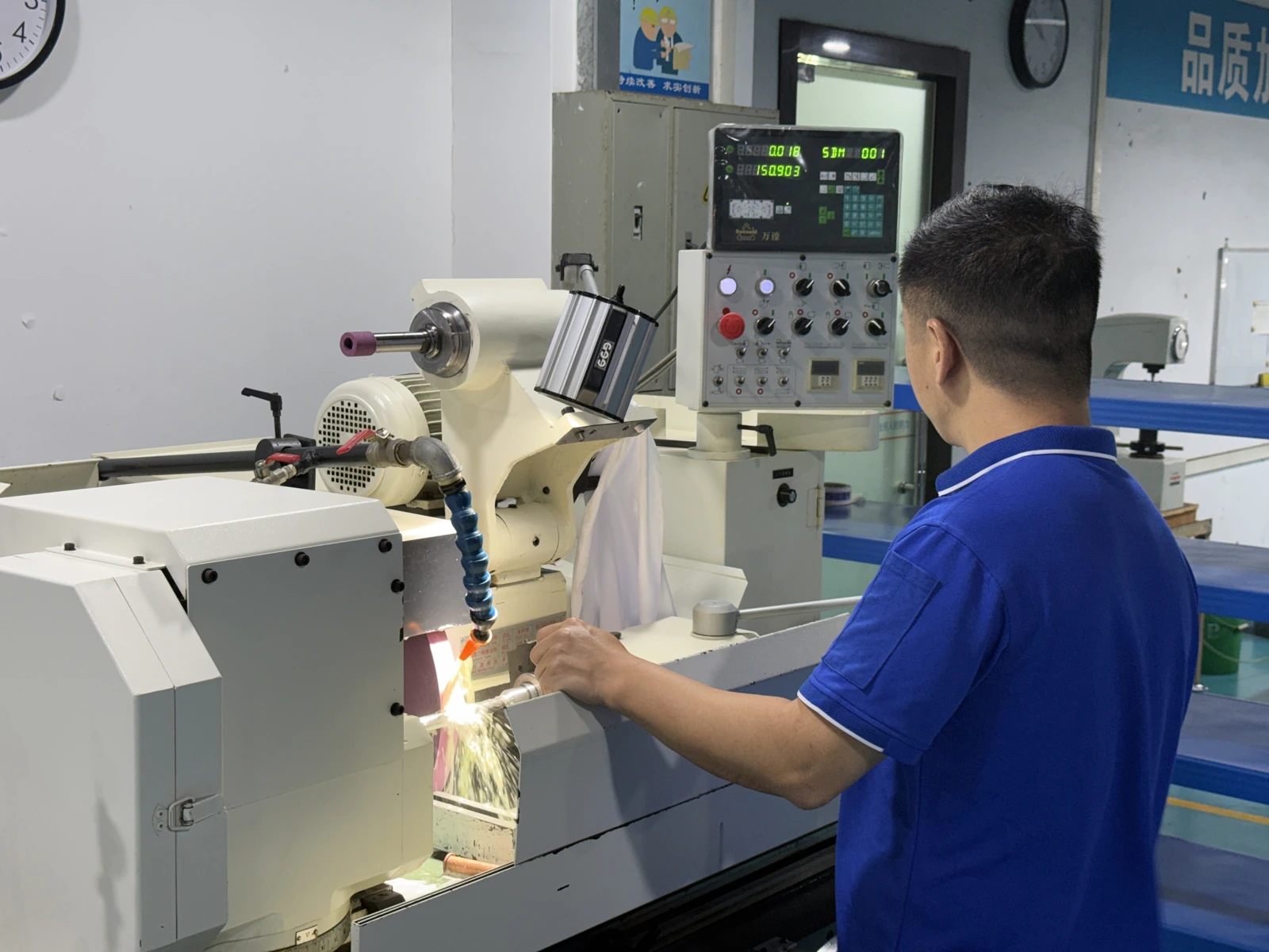
Plan the process sequence
Define what each operation must preserve before work starts.
- Identify stock condition and setup datums.
- Relate turning, grinding or EDM to the feature.
- Preserve forming edges during finishing.
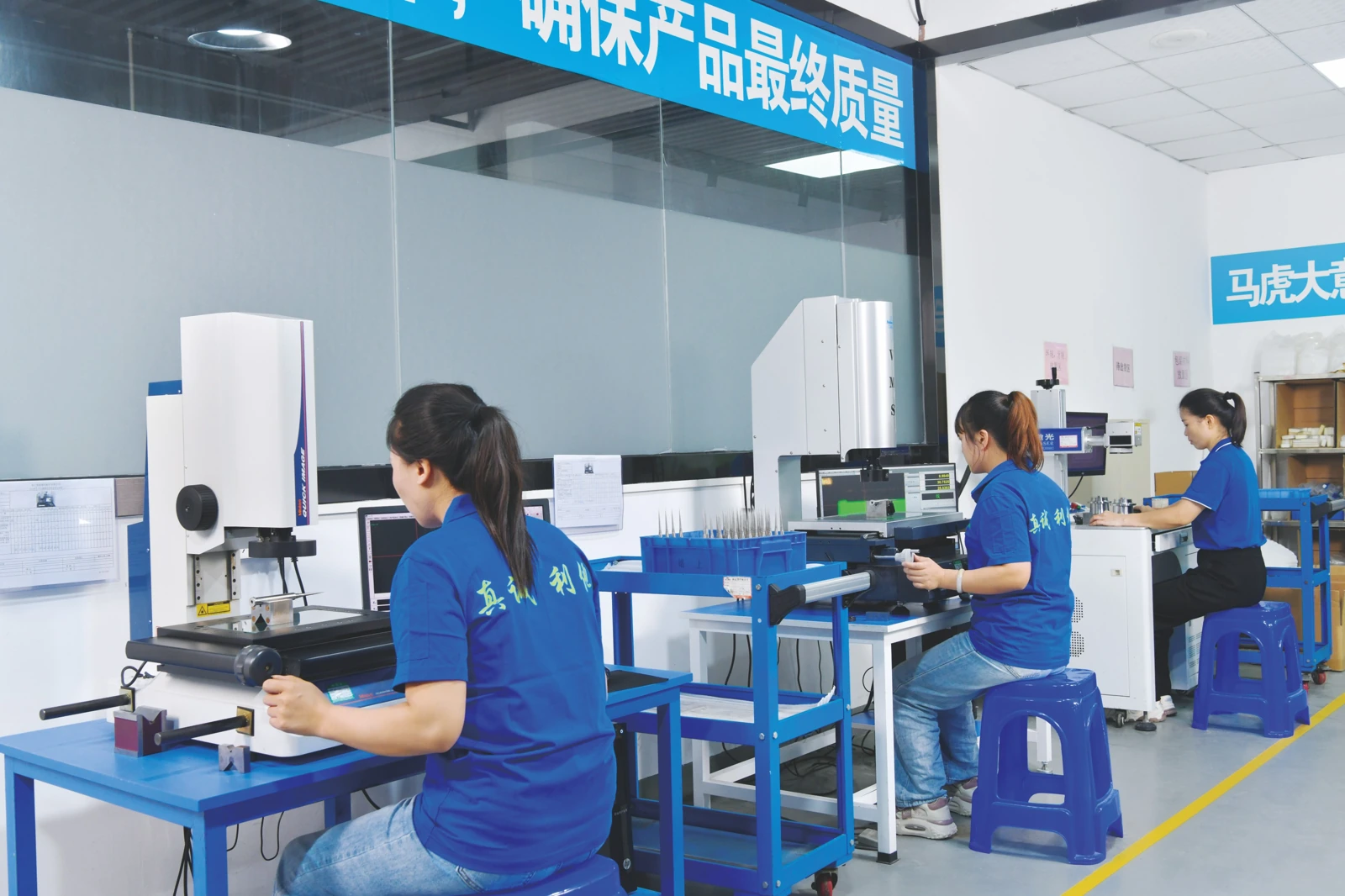
Agree the checks
Connect acceptance requirements to a suitable measurement method.
- State critical dimensions and reference faces.
- Review access and support for slender features.
- Agree report coverage and part identification.
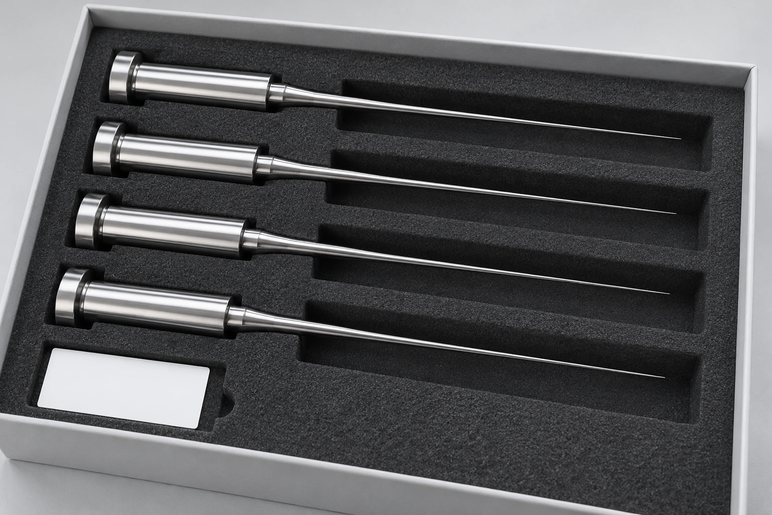
Protect the functional surfaces
Specify set identification and packing contact zones.
- Separate fine tips and polished surfaces.
- Support the shank rather than the working length.
- State cleanliness and protection requirements.
LET’S REVIEW YOUR COMPONENT
Send the drawing.
Show what matters.
Share the component geometry and its role in the mold. Define the manufacturing, inspection and handling requirements for your medical or laboratory mold components.
Include the information available. Missing specifications can be clarified during the review.
Your drawing-review checklist
0 / 4 ready
This checklist helps prepare your inquiry. It does not submit a request.
PRACTICAL QUESTIONS
Before you
send the RFQ.
Details that turn a component drawing into a clear review scope.
Do you supply mold components or molded consumables?
This page covers drawing-based mold components such as core pins, inserts and sleeves. The complete mold and laboratory consumable images explain the application context. Identify the component scope in your RFQ.
What information matters most for a slender core?
Include the forming profile and end detail, working diameter, unsupported length, locating surfaces and support arrangement. Relate the required dimensional and geometric checks to the drawing datums.
Which material and inspection documents should I request?
Specify the exact grade and condition, then list required certificates, treatment records and dimensional reports. Identify critical characteristics and any part-level or set-level traceability needs.
How should replacement parts and matched sets be identified?
Provide the current drawing revision and mating geometry. State quantity by part number and identify any matched or interchangeable set requirements. Agree which dimensions need comparison across the set.